Sections of the site
Editor's Choice:
- Brilev Sergei: biography and family Ordinary person Sergei Brilev: family, wife
- How to get into the “Housing Question” or “Repair School” and get free repairs NTV repairs at your dacha
- Paradoxes of the Adzhimushkay tragedy
- Sergei Mikheev, biography, news, photos Sergei Mikheev political scientist write a letter
- Everything you need to know about bacteria
- An example of filling out section 1 of form 6 personal income tax
- Semiconductor diodes and transistors, their areas of application
- How to choose the right flux
- What are quasars and what are their functions in the Universe?
- English words that cannot be translated
Advertising
| Power unit. Simple power supply Final assembly of a switching voltage converter |
|
Somehow recently I came across a diagram on the Internet that was very simple block power supply with voltage regulation. The voltage could be adjusted from 1 Volt to 36 Volt, depending on the output voltage on the secondary winding of the transformer. Take a close look at the LM317T in the circuit itself! The third leg (3) of the microcircuit is connected to capacitor C1, that is, the third leg is INPUT, and the second leg (2) is connected to capacitor C2 and a 200 Ohm resistor and is an OUTPUT. Using a transformer from mains voltage 220 Volts we get 25 Volts, no more. Less is possible, no more. Then we straighten the whole thing with a diode bridge and smooth out the ripples using capacitor C1. All this is described in detail in the article on how to obtain constant voltage from alternating voltage. And here is our most important trump card in the power supply - this is a highly stable voltage regulator chip LM317T. At the time of writing, the price of this chip was around 14 rubles. Even cheaper than a loaf white bread. Description of the chipLM317T is a voltage regulator. If the transformer produces up to 27-28 volts on the secondary winding, then we can easily regulate the voltage from 1.2 to 37 volts, but I would not raise the bar to more than 25 volts at the transformer output. The microcircuit can be executed in the TO-220 package:
or in D2 Pack housing
It can pass a maximum current of 1.5 Amps, which is enough to power your electronic gadgets without voltage drop. That is, we can output a voltage of 36 Volts with a current load of up to 1.5 Amps, and at the same time our microcircuit will still output 36 Volts - this, of course, is ideal. In reality, fractions of volts will drop, which is not very critical. With a large current in the load, it is more advisable to install this microcircuit on a radiator. In order to assemble the circuit, we also need a variable resistor of 6.8 Kilo-Ohms, or even 10 Kilo-Ohms, as well as a constant resistor of 200 Ohms, preferably from 1 Watt. Well, we put a 100 µF capacitor at the output. Absolutely simple scheme! Assembly in hardwarePreviously, I had a very bad power supply with transistors. I thought, why not remake it? Here is the result ;-)
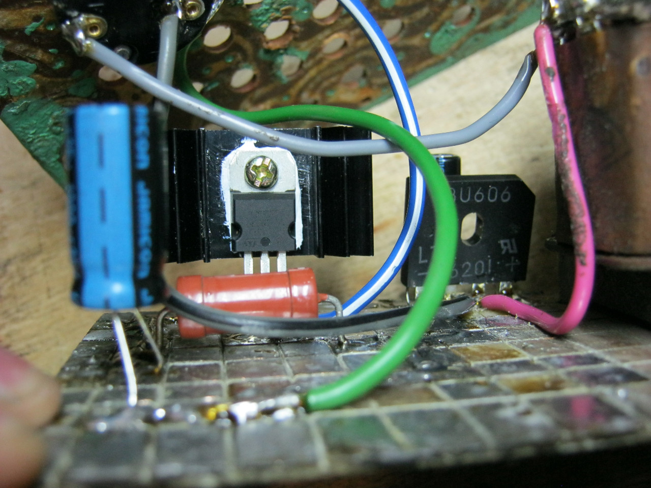
Here we see the imported GBU606 diode bridge. It is designed for a current of up to 6 Amps, which is more than enough for our power supply, since it will deliver a maximum of 1.5 Amps to the load. I installed the LM on the radiator using KPT-8 paste to improve heat transfer. Well, everything else, I think, is familiar to you.
And here is an antediluvian transformer that gives me a voltage of 12 volts on the secondary winding.
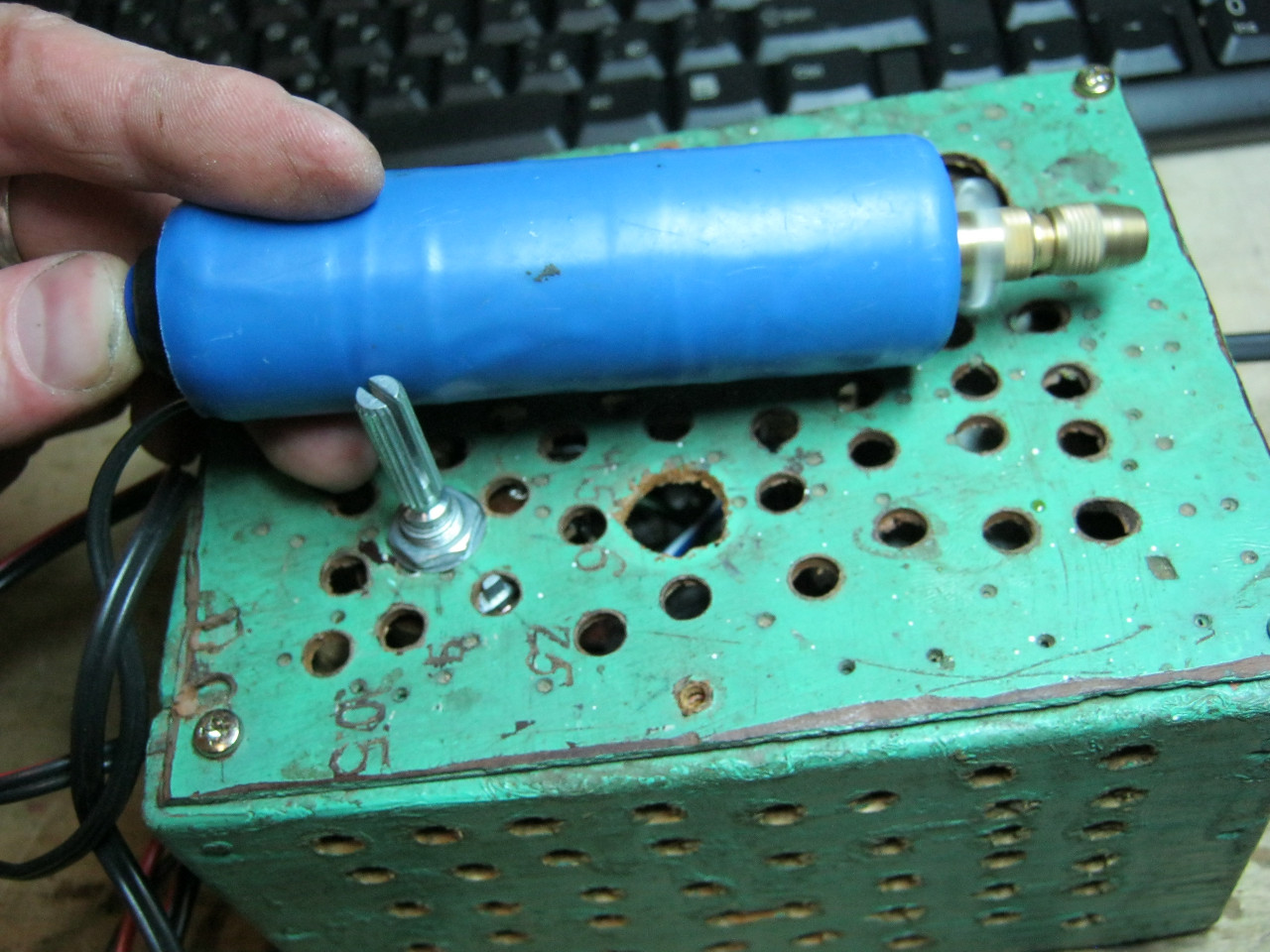
We carefully pack all this into the case and remove the wires.
So what do you think? ;-)
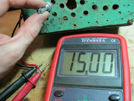
The minimum voltage I got was 1.25 Volts, and the maximum was 15 Volts.
I set any voltage, in this case the most common are 12 Volts and 5 Volts
Everything works great! This power supply is very convenient for adjusting the speed of a mini drill, which is used for drilling circuit boards.
Analogues on AliexpressBy the way, on Ali you can immediately find a ready-made set of this block without a transformer.
Too lazy to collect? You can buy a ready-made 5 Amp for less than $2:
You can view it at this link. If 5 Amps is not enough, then you can look at 8 Amps. It will be enough for even the most seasoned electronics engineer:
This review of the channel “Reviews of parcels and homemade products from jakson” is about a simple circuit of a bipolar power supply with an output voltage of 15 volts. The circuit that we will assemble does not require many parts. The main thing is to find 2 regulators 7815 and 7915. They can be ordered in China. Radio components and boards can be purchased with free delivery in this Chinese store. As a result, the output should be plus 15 and minus 15 volts of bipolar power supply. To do this, we need a special transformer, at the output of which we can obtain bipolar power with a midpoint. This can be achieved in two ways. For example, if a transformer is built in such a way that between its two contacts (in our case +15 and -15) there is a middle point, which is the contact of the middle of the secondary winding. The voltage between the middle and first contacts will be 15 volts, and between the middle and last contacts will also be 15. Between the first and last - 30 volts. If the design of the transformer does not provide the point we need, we can take two secondary windings with the same voltage. The midpoint between them will be the midpoint of our 2-polar power supply. Let's do so. There will be not 2 windings, but 4, since there are many secondary windings in this transformer, we will connect several to obtain the required voltage. An old Soviet military transformer will be used, which is over 30 years old. Despite this, it works great and essentially there is nothing to break, since it is completely flooded and sealed. Perhaps its quality will be even better than that of modern Chinese transformers. But its power is only 60 watts.
The assembly of the block will be carried out on a breadboard printed circuit board good quality. The diode bridge contains IN 5408 diodes. There will be enough of them to spare. We will also need four electrolytic capacitors. Two of them are 2200 microfarads, 25 volts and the other are 100 microfarads, 35 volts. Two 0.1 µF capacitors. Also the regulators discussed above. When soldering the regulators, be careful, as they have different pinouts. There are two LEDs in the circuit - indicators that are not particularly needed; they can be omitted. Discussion
To compensate for the voltage drop on the output transistors, within 1 Volt, the middle leg of the stabilizer is connected to the negative wire through diodes, which raise the voltage at the output of the microcircuit, thereby providing a maximum output voltage of the power supply up to 15 Volts, when installed variable resistor to the top position according to the diagram, without using VD1 and VD2, the control limit voltage is approximately 14 volts. To stabilize the output voltage when the transistors are very hot, we recommend installing these diodes on the same cooling radiator together with VT2. In this power supply circuit, very common radio components are used, but they are easily replaced with elements with similar parameters. The transformer can be installed of any type, but of sufficient power, with a voltage on the secondary winding of 15 to 20 Volts and a current of at least 10 Amperes. Capacitors are suitable with a minimum limit voltage of at least 50 Volts, any resistors with a power of 0.25 Watt, variable resistor R1 in the circuit, it is advisable to use it with a linear adjustment characteristic, so that a uniform voltage scale can be applied to the power supply housing. The diode bridge can be replaced with four diodes, for a current of at least 10 Amps, the stabilizer microcircuit has many analogues, the main parameter when choosing it will be an output voltage of 15 Volts. Powerful transistors can be replaced with imported analogues, with a sufficient transfer coefficient h21e, to ensure maximum current at the output of the circuit. The power supply does not require any setup; it works well immediately after assembling the circuit; when turned on, the output voltage should be smoothly regulated by the variable resistor R1 from 0 to 15 Volts. To ensure reliable operation under heavy loads, install the output transistor VT2 and the diode bridge VDS-1 on a cooling radiator of sufficient area; the remaining radio elements practically do not heat up and can be operated without cooling. Every radio amateur and designer will find a use for this device; a power supply built according to this scheme is very useful when setting up various radio circuits, testing low-voltage equipment that changes its parameters when adjusting the supply voltage, and so on... If you connect an ammeter to the output of the device, then it can be successfully used to charge car batteries, while controlling the charging current. How to assemble a simple power supply and a powerful voltage source yourself.
Power supply circuit 12V 30A. Power supply 3 - 24V
The power supply circuit gives adjustable voltage in the range from 3 to 25 volts, with a maximum load current of up to 2A, if you reduce the current-limiting resistor to 0.3 ohms, the current can be increased to 3 amperes or more. 1.5 V power supply circuit
The power supply circuit to obtain a voltage of 1.5 volts uses a step-down transformer, a bridge rectifier with a smoothing filter and an LM317 chip. Diagram of an adjustable power supply from 1.5 to 12.5 V
Power supply circuit with output voltage regulation to obtain voltage from 1.5 volts to 12.5 volts; the LM317 microcircuit is used as a regulating element. It must be installed on the radiator, on an insulating gasket to prevent a short circuit to the housing. Power supply circuit with fixed output voltage
Power supply circuit with a fixed output voltage of 5 volts or 12 volts. The LM 7805 chip is used as an active element, LM7812 is installed on a radiator to cool the heating of the case. The choice of transformer is shown on the left on the plate. By analogy, you can make a power supply for other output voltages. 20 Watt power supply circuit with protection
The circuit is designed for a small transceiver homemade, by DL6GL. When developing the unit, the goal was to have an efficiency of at least 50%, a nominal supply voltage of 13.8V, maximum 15V, for a load current of 2.7A.
To prepare the power supply for operation (the 6.3A fuse is not yet involved), set the output voltage to, for example, 12.0V. Load the unit with a load; for this you can connect a 12V/20W halogen lamp. Set R2 so that the voltage drop is 0.7V (the current should be within 3.8A 0.7=0.185Ωx3.8). Homemade 3.3v power supplyIf you need a powerful power supply of 3.3 volts, then it can be made by converting an old power supply from a PC or using the above circuits. For example, replace a 47 ohm resistor of a higher value in the 1.5 V power supply circuit, or install a potentiometer for convenience, adjusting it to the desired voltage. Transformer power supply on KT808Many radio amateurs still have old Soviet radio components that are lying around idle, but which can be successfully used and they will serve you faithfully for a long time, one of the well-known UA1ZH circuits that is floating around the Internet. Many spears and arrows are broken on forums when discussing which is better field-effect transistor or ordinary silicon or germanium, what temperature of crystal heating will they withstand and which one is more reliable?
Given that correct installation, output voltage drop does not exceed 0.1 volt Power supply for 1000V, 2000V, 3000VIf we need to have a high voltage DC source to power the transmitter output stage lamp, what should we use for this? On the Internet there are many different power supply circuits for 600V, 1000V, 2000V, 3000V.
The circuit has a step-up anode transformer T1 (for the required power, for example 2500 VA, 2400V, current 0.8 A) and a step-down filament transformer T2 - TN-46, TN-36, etc. To eliminate current surges during switching on and protection diodes when charging capacitors, switching is used through quenching resistors R21 and R22. More on the topicTransformer power supply 13.8 volts 25 A for a HF transceiver with your own hands. Prologue. I have two multimeters, and both have the same drawback - they are powered by a 9-volt Krona battery. I always tried to have a fresh 9-volt battery in stock, but for some reason, when it was necessary to measure something with an accuracy higher than that of a pointer instrument, the Krona turned out to be either inoperative or only lasted for a few hours of operation. The procedure for winding a pulse transformer. It is very difficult to wind a gasket onto a ring core of such small dimensions, and winding a wire onto a bare core is inconvenient and dangerous. The wire insulation may be damaged by the sharp edges of the ring. To prevent the turns from running apart when laying the wire, it is useful to cover the core with a thin layer of “88N” glue and dry it before winding.  First, the secondary windings III and IV are wound (see converter diagram). They need to be wound into two wires at once. The coils can be secured with glue, for example, “BF-2” or “BF-4”. I did not have a suitable wire, and instead of a wire with a calculated diameter of 0.16 mm, I used a wire with a diameter of 0.18 mm, which led to the formation of a second layer of several turns. Then, also in two wires, primary windings I and II are wound. The turns of the primary windings can also be secured with glue.  I assembled the converter using the hinged mounting method, having previously connected the transistors, capacitors and transformer with cotton thread. The input, output and common bus of the converter were connected with a flexible stranded wire. Setting up the converter.Tuning may be required to set the desired output voltage level. I selected the number of turns so that at a battery voltage of 1.0 Volts, the output of the converter would be about 7 Volts. At this voltage, the low battery indicator lights up in the multimeter. This way you can prevent the battery from being discharged too deeply. If instead of the proposed KT209K transistors, others are used, then the number of turns of the secondary winding of the transformer will have to be selected. This is due to the different magnitude of the voltage drop across p-n junctions at various types transistors. I tested this circuit using KT502 transistors with unchanged transformer parameters. The output voltage dropped by a volt or so. You also need to keep in mind that the base-emitter junctions of transistors are also output voltage rectifiers. Therefore, when choosing transistors, you need to pay attention to this parameter. That is, the maximum permissible base-emitter voltage must exceed the required output voltage of the converter.  If generation does not occur, check the phasing of all coils. The dots on the converter diagram (see above) mark the beginning of each winding. To avoid confusion when phasing the coils of the ring magnetic circuit, take as the beginning of all windings, For example, all leads coming out from the bottom, and beyond the end of all windings, all leads coming out from the top. Final assembly of a pulse voltage converter. Before final assembly, all elements of the circuit were connected with stranded wire, and the circuit's ability to receive and transmit energy was tested. To prevent short circuits, the pulse voltage converter was insulated on the contact side with silicone sealant.  Then all the structural elements were placed in the Krona body. To prevent the front cover with the connector from being recessed inside, a celluloid plate was inserted between the front and back walls. After which, the back cover was secured with “88N” glue.  To charge the modernized Krona, we had to make an additional cable with a 3.5mm jack plug at one end. At the other end of the cable, to reduce the likelihood of a short circuit, standard device sockets were installed instead of similar plugs. Refinement of the multimeter. The DT-830B multimeter immediately started working with the upgraded Krona. But the M890C+ tester had to be slightly modified. The fact is that most modern multimeters have an automatic power-off function. The picture shows part of the multimeter control panel where this function is indicated.  The Auto Power Off circuit works as follows. When the battery is connected, capacitor C10 is charged. When the power is turned on, while capacitor C10 is discharged through resistor R36, the output of comparator IC1 is held at a high potential, which causes transistors VT2 and VT3 to turn on. Through the open transistor VT3, the supply voltage enters the multimeter circuit. As you can see, for normal operation of the circuit, you need to supply power to C10 even before the main load turns on, which is impossible, since our modernized “Krona”, on the contrary, will turn on only when the load appears.  In general, the whole modification consisted of installing an additional jumper. For her, I chose the place where it was most convenient to do this. Unfortunately, the element designations on electrical diagram did not match the markings on the printed circuit board of my multimeter, so I found the points for installing the jumper this way. By dialing, I identified the required output of the switch, and identified the +9V power bus using the 8th leg of the operational amplifier IC1 (L358). Small details.It was difficult to purchase just one battery. They are mostly sold either in pairs or in groups of four. However, some kits, for example, “Varta”, come with five batteries in a blister. If you are as lucky as I am, you will be able to share such a set with someone. I bought the battery for only $3.3, while one “Krona” costs from $1 to $3.75. There are, however, also “Crowns” for $0.5, but they are completely stillborn. |


| Read: |
|---|
Popular:
How to calculate magnification
|
New
- How to get into the “Housing Question” or “Repair School” and get free repairs NTV repairs at your dacha
- Paradoxes of the Adzhimushkay tragedy
- Sergei Mikheev, biography, news, photos Sergei Mikheev political scientist write a letter
- Everything you need to know about bacteria
- An example of filling out section 1 of form 6 personal income tax
- Semiconductor diodes and transistors, their areas of application
- How to choose the right flux
- What are quasars and what are their functions in the Universe?
- English words that cannot be translated
- Abbreviations in English: common and informal


