Sections of the site
Editor's Choice:
- Pork roll with filling
- Soup with melted cheese and chicken breast
- Step-by-step recipe for cooking broccoli in batter with photo Broccoli batter
- Lush sweet buns (7 recipes)
- Tortilla - what kind of Mexican dish is it and how to properly prepare it at home with photos
- Wheat tortilla Homemade tortilla recipe
- Calorie content of 1 eclair with custard
- Canned fish soup sardines with rice
- Dance with a woman in a dream
- Why dream of dancing with a guy
Advertising
| How are roller shutters indicated in the drawing? Symbols on BTI plans |
|
When a real estate property, for example, an apartment building, is put into operation, an inventory must be carried out in order to legally record the available space. For this purpose, employees of the Technical Inventory Bureau measure the premises. And then, based on the data obtained, a floor plan of the building is drawn up.
The BTI plan shows the exact dimensions of the rooms and graphically marks the following elements:
All these elements have symbols on the BTI floor plan. Types of BTI documentsTo coordinate redevelopments, the following types of documents issued by the Bureau of Technical Inventory are used. Floor plan and explication You can find out more about what these documents are, how and where they can be ordered from a separate articles. Here we just note that these are the simplest BTI documents, which provide a minimum of information about the object. A floor plan is a diagram of an object, presented as a drawing with special symbols. When entering the apartment, its number is indicated on the drawing. In addition, the sheet has a stamp of the BTI department that issued the document. Also, the BTI floor plan contains information about the legal address of the building and the floor on which the premises are located, as well as the date of its last inspection. An explanation is attached to the floor plan, which provides a list and purpose of all premises of the facility - residential and auxiliary - indicating their area and ceiling height.
Floor plan with explication Thus, a floor plan with an explanation is two sheets of the same format, one of which reflects the floor plan in the form of a drawing, and the other a table with the characteristics of rooms and premises. BTI technical passport A technical passport is a document that is specifically designed for coordinating redevelopments. Technical passport with BTI plan We also have a separate section about it. But speaking in general, this is a more detailed document, which, in addition to the floor plan and explication, contains information about the house where the premises are located (series, material of walls and ceilings, number of floors of the building, number of apartments, year of construction, etc.) , address plan, etc. Floor plan with explication before redevelopment This document is used to legitimize redevelopment that has already been made, if illegal changes are indicated in the BTI documents with red lines. Read more about this. In general, this document is similar to a floor plan with an explanation, but has a special mark “before redevelopment” or “before refurbishment”.
Floor plan with explication before redevelopment Any room consists of structural elements that have their own name, purpose, size, shape and other characteristics. On the BTI plans they are reflected in the form of conventional graphic symbols, which are not always clear to the owners of the premises. And since everyone who has decided to redevelop their apartment and wants to do it legally will need to deal with some of these documents, it is important to be able to understand how and what is indicated on them. Therefore, next we will analyze the designations on the BTI plans. Description of symbols on BTI plansLet us immediately note that the BTI designations do not depend on the type of document. That is, one or another element of the drawing is indicated in the same way both in the technical passport and on the floor plan. First of all, owners are interested in the following question: how are load-bearing walls designated on the BTI plan? Many people believe that in the drawing thick black lines mark the main walls, and thin black lines mark the non-load-bearing partitions. But this doesn't always happen. Therefore, it is impossible to determine from the BTI plan which walls are load-bearing and which are non-load-bearing. In any case, the average person certainly cannot do this on their own, unless they turn to a specialist for help. If the room was performed uncoordinated redevelopment, which became known to the BTI, then after the necessary measurements have been carried out by an employee of the Technical Inventory Bureau, all changes made in the drawing will be marked with red lines. Doorways are designated as follows: within the boundaries of the line to indicate the partition, two small marks in the form of parallel lines are applied perpendicularly. If there is a door leaf, another parallel line is drawn between them, extending beyond the wall. This is exactly the designation of the door on the BTI plan. In a similar way, information about the presence and location of window openings is included in the floor plan. The thickest lines on the drawing mark the façade walls, on which the windows are marked by two parallel lines with perpendicular limits on both sides showing their width. The numbering and area of the room are displayed as a fractional number, where the numerator is the room number, and the denominator is its area. In addition, the location of plumbing fixtures and kitchen stoves in the “wet” areas of the apartment is indicated on the BTI plans. Most often, you can guess which plumbing fixtures are indicated on the drawing by looking at the contours of the geometric shapes that represent them. And you can also guess about the designation of the electric stove on the BTI plan.
It is easiest to decipher the symbols on the BTI plan using specific examples.
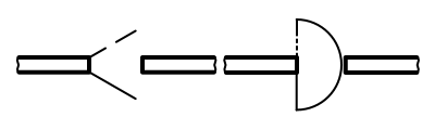
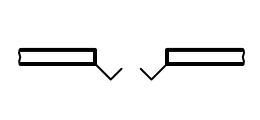
According to GOST 21.201–2011 to indicate on construction drawings such structural elements of buildings as window sashes facades, special symbols are used. However, the number of bindings themselves is not shown graphically. To indicate those bindings that open outward, a thin solid line is used in the corresponding images, and those that open inward are used a thin dashed line. If a binding is not hung on the binding shown on the construction drawing, then the top of the corresponding sign should be directed towards it. As for architectural drawings that depict window blocks, then they must be part of the design documentation or documentation of the order for the manufacture of a particular product. On those construction drawings that are made on a scale of 1: 200 or less, quarters are not shown.
A window frame is a building structure necessary to strengthen and divide the glazing field and decorate it. It consists of several elements: transoms, windows, sashes. The window frame, in turn, together with the window frame, makes up the window block. Window units are designed in such a way that during their operation it is possible to replace glass, double-glazed windows, sealing gaskets, window devices, while maintaining the integrity of these parts. All opening elements of windows installed in residential buildings must open only to the inside of the premises. For individual structures (for example, windows that are installed in the premises of the first floors of buildings or overlook balconies), modern standards, building codes and regulations provide for the possibility of opening outward. In order to ensure ventilation of the room, in the windows with which they are equipped, either transoms, or casement windows, or regular windows are installed, or special supply valves are installed in them. Transoms can be either openable or blind; they are usually mounted above the sashes, in the upper parts of window frames. To secure an openable transom in the window frame, a horizontal impost is used. If the box is wide enough, then a vertical impost is installed in it so that the edges of the vertical bars of the sashes adjoin it. Based on the number of sashes in one row, windows are divided into:
As for the design of window frames, they are:
In window blocks with paired sashes there are two of them: external and internal. They are connected to each other, and the inner one, in addition, is hung on the box using hinges. Thus, the sashes, connected to each other by fastening elements, form a binding with a fairly high rigidity. The design of a separate window block includes a frame, vents, transoms and sashes that open either in one direction or in different directions. Separate-paired window units are a combination of windows with separate and paired sashes. In these windows, the outer sashes are single, and the inner sashes are double. In addition, a term such as “split-pair window sash” is often used to refer to a structure that divides a window into separate parts. Windows are important elements of the interiors and exteriors of buildings. Often those of them that have an original, non-standard shape are their decorations, while simultaneously playing their utilitarian role. Windows are necessary in order to create comfort in the house; they must have a design that ensures savings in money spent on heating the interior. Door And window openings buildings simultaneously perform two functions: utilitarian and aesthetic. From a practical point of view, they are the elements that provide access to the building for people, light and air. At the same time, door and window openings largely determine the architectural appearance of buildings. According to GOST 21.201-2011 on construction drawings to indicate openings and openings, special markings must be used. Usually, when drawing an opening that is supposed to be made in a ceiling or partition, a broken line is drawn inside, which otherwise may not be done if it is clearly clear what exactly is being displayed. In cases where the hole or opening According to the designers' plans, they should be sealed, then dotted lines are used to depict them, and when depicting these elements of buildings in sections, shading is used. The explanatory notes indicate the material of the bookmark. Simplified image method window openings in prefabricated structures (for example, reinforced concrete slabs) they are used when the scale of the drawing is 1: 200 or smaller. In this case, the quarters are not depicted. Openings and openings in rooms are mainly divided into window, door and ventilation. Holes and openings are made in walls made from a wide variety of materials: stone, concrete, wood, brick, foam and aerated concrete, etc. When placing all kinds of window and door openings, designers must take into account such a factor as the convenience of furniture placement for any type of planning solutions. In order to correctly position the holes through which air is removed or supplied, it is necessary to take into account their spatial position relative to each other. It should be such that air flows freely through them, both into and outside the premises. When constructing the walls of modern buildings, the manual masonry method with vertical and horizontal bandaging of seams is used. Door and window openings of the walls are made with quarters adjacent to the outside along the vertical, as well as the upper edges. The quarters enable reliable and tight installation in the openings of window frames. They allow the use of various modern sealing materials. In addition, the presence of quarters looks very good based on the results of the work. The purpose of windows as elements of buildings is to ensure the penetration of natural light into the premises and their ventilation. Doors are necessary to provide access to the building and communication between rooms isolated from each other. The windows of modern buildings are usually double glazed. They can be single, double or tricuspid. In addition to them, drains made of galvanized steel sheet, as well as window sill plates, are also installed in the openings. Cement-sand mortar is used to construct slopes. Doors installed in modern buildings are glazed and solid. Recently, plastic has been widely used for the manufacture of windows and doors. The windows are equipped with sealed double-glazed windows, which are installed between PVC profiles. Inside these profiles there are cavities, the number of which may vary. They provide good heat and sound insulation. To make it even better, the windows must be equipped with double-glazed windows. Note doors And gate on drawings used in construction, must be carried out according to GOST 21.201-2011. In accordance with this document, it is necessary to use special graphics. In those drawings that are made on a scale of 1:400 and smaller, the door leaves and the direction of their opening are not shown. If the scale of the images doors And gate is 1:50 or more, then when depicted on construction drawings it is necessary to indicate such elements as quarters, thresholds, etc.
One of the most common elements of buildings and structures are doors. They can have a wide variety of designs, but the most common are:
Based on the material they are made of, they are classified into:
To install doors, frames are installed in doorways. If wood is used for this purpose, then such structures are made from bars and then attached to the wall. Wooden panels are usually made from a material such as laminated boards. Often used for this purpose Chipboard, which are finished with facing materials. Metal door frames and their frames are made from galvanized cold-formed steel profiles, which are subsequently painted to give the structure an aesthetic appearance and protection against corrosion. The door leaf of metal doors consists of one or two steel sheets, a frame and stiffeners. The structural elements of glass door leaves are a frame made of aluminum or steel profile, and a leaf made of so-called “stalinite” (that is, tempered glass, characterized by increased strength). According to current norms and standards, all entrance doors to buildings and apartments must open outward, that is, in the direction of movement to the street. This is necessary in order to facilitate the evacuation of people from buildings in the event of various emergencies (for example, fires). Wooden plugs treated with antiseptics are used to secure door frames in openings. They are installed directly into reinforced concrete panels at the manufacturing stage of these structures. If the doors are external, then they are installed together with thresholds, and if internal, then without them. To hang door panels on door frames, hinges are used. If the door is wide open, it is very easy and simple to remove it from its hinges. In order to avoid doors being open or slamming, special devices called “diplomat” are used. They serve to keep the door closed, and if they open, then return it smoothly, without blows. In addition, the doors are equipped with mortise locks, latches and handles. Entrance doors are often equipped with combination locks. GatesGates are functional building structures that are used to restrict access to a particular territory. They can play both a strictly utilitarian and decorative role. In the latter case, they often do not have doors and are simply an arch. If the gate is intended for the passage of vehicles, then its dimensions are taken into account during their development and production. According to their design, gates can be swing, rotary, sliding, sliding, up-and-over and lift-up. The simplest in design and most common are swing and sliding gates. There are also swinging gates, in which the leaves are made of sheets of rubber or elastic transparent plastic. They are most often installed in industrial buildings and can significantly reduce heat loss. According to GOST 21.201–2011 to indicate on construction drawings such structural elements of buildings as window sashes facades, special symbols are used. However, the number of bindings themselves is not shown graphically. To indicate those bindings that open outward, a thin solid line is used in the corresponding images, and those that open inward are used a thin dashed line. If a binding is not hung on the binding shown on the construction drawing, then the top of the corresponding sign should be directed towards it. As for architectural drawings that depict window blocks, then they must be part of the design documentation or documentation of the order for the manufacture of a particular product. On those construction drawings that are made on a scale of 1: 200 or less, quarters are not shown.
A window frame is a building structure necessary to strengthen and divide the glazing field and decorate it. It consists of several elements: transoms, windows, sashes. The window frame, in turn, together with the window frame, makes up the window block. Window units are designed in such a way that during their operation it is possible to replace glass, double-glazed windows, sealing gaskets, window devices, while maintaining the integrity of these parts. All opening elements of windows installed in residential buildings must open only to the inside of the premises. For individual structures (for example, windows that are installed in the premises of the first floors of buildings or overlook balconies), modern standards, building codes and regulations provide for the possibility of opening outward. In order to ensure ventilation of the room, in the windows with which they are equipped, either transoms, or casement windows, or regular windows are installed, or special supply valves are installed in them. Transoms can be either openable or blind; they are usually mounted above the sashes, in the upper parts of window frames. To secure an openable transom in the window frame, a horizontal impost is used. If the box is wide enough, then a vertical impost is installed in it so that the edges of the vertical bars of the sashes adjoin it. Based on the number of sashes in one row, windows are divided into:
As for the design of window frames, they are:
In window blocks with paired sashes there are two of them: external and internal. They are connected to each other, and the inner one, in addition, is hung on the box using hinges. Thus, the sashes, connected to each other by fastening elements, form a binding with a fairly high rigidity. The design of a separate window block includes a frame, vents, transoms and sashes that open either in one direction or in different directions. Separate-paired window units are a combination of windows with separate and paired sashes. In these windows, the outer sashes are single, and the inner sashes are double. In addition, a term such as “split-pair window sash” is often used to refer to a structure that divides a window into separate parts. Windows are important elements of the interiors and exteriors of buildings. Often those of them that have an original, non-standard shape are their decorations, while simultaneously playing their utilitarian role. Windows are necessary in order to create comfort in the house; they must have a design that ensures savings in money spent on heating the interior. Individual elements of buildings (window and door openings, staircases) and parts of internal equipment (sanitary and heating devices, etc.) are shown in the drawings using conventional graphic symbols.
Rice. 263. Conventional graphic images of window and door openings Rice. 264. Graphic symbols of stairs 39.1. Window and door openings. Figure 263 shows conventional graphic symbols and visual images of window and door openings on sections and plans of buildings. As you can see, walls are depicted in sections with solid main lines, window openings - with solid thin lines. In place of the doorways, no lines are drawn in the plan, but they show the door leaf and the direction in which the door opens. 39.2. Stairwells. Figure 264 shows the designation of the stairs: flight of stairs in section (Fig. 264, a), lower flight in plan (Fig. 264, b), intermediate flight (Fig. 264, c), upper flight (Fig. 264, d) . 39.3. Heating devices, sanitary equipment. Figure 265 contains explanatory inscriptions and corresponding symbols of heating devices and sanitary equipment.
Rice. 265. Heating and sanitary devices Rice. 266. Graphic designations of materials in sections Chimneys are depicted on the plan as rectangles, half of which are blackened diagonally. For ventilation ducts, this half is not blackened (only the diagonal is drawn). A solid fuel stove is depicted as a rectangle. The dash shows the firebox. A gas stove is depicted as a rectangle with a diagonal. The slab is also depicted as a rectangle, but with two circles. All conventional images are outlined with thin lines. They are carried out in the scale accepted for this drawing. 39.4. Designation of materials in sections. Figure 266 shows some graphical designations of materials in sections established by the standard. In construction drawings, it is allowed to designate any material as metal on sections of a small area or not use the designation at all, giving an explanatory inscription in the drawing field. In architectural and construction drawings, in order to make them more clear, visual and readable, conventional graphic symbols according to GOST 5401-50 are used for building materials, building elements, sanitary equipment, etc., which makes it possible to shorten the explanatory inscriptions on the drawings. Symbols for building materials, most often The figure shows the symbols of some building materials most often used in the construction of buildings. Brick or stone masonry is indicated in the section in the drawings by straight parallel strokes with a slope of 45° to the horizon. The distances between strokes depend on the scale of the drawing. In small drawings, gaps of about 1 mm are taken, in large ones they are increased to 2 - 2.5 mm. The refractory brickwork is hatched into a square check. In large-scale drawings, the metal parts of structures are shaded in the same way as brick, but a little thicker. On small-scale drawings and in general when the thickness of the cut part in the drawing is less than 2 mm, a solid black fill is made with ink. Wooden parts in a cross section (from the end) are hatched with circular and radial lines, and in a longitudinal section they are hatched as the fibers go in the wood, and depict the actual arrangement of the layers of wood in nature. Wooden parts that do not fall into the cut are not hatched. Thin layers of various insulating and cushioning materials (tar paper, cardboard, cork, asbestos, hemp, asphalt, etc.) are depicted as a solid black fill with an explanatory inscription. Concrete is represented by dots with irregular circles between them. The circles are made by hand with a pen. If two layers of different composition come into contact, then they are separated by a horizontal line. The composition of concrete is indicated by inscriptions. Reinforced concrete, i.e. concrete reinforced with iron rods (reinforcement) embedded in it, is indicated by ordinary shading and circles. Water is depicted with intermittent horizontal parallel strokes, with the spaces between them increasing as they move away from the surface. Walls and partitions are depicted with two parallel lines, the space between which is shaded with thin oblique lines (at an angle of 45°), sometimes filled with ink, and sometimes left without shading or filling. Windows and doors are depicted as wall openings of appropriate sizes, which are not shaded, but are depicted as parallel lines for frames and perpendicular for door leaves. The part of the door that opens is called the door leaf.
a - external door; Stairs can be internal, if they are located in a special enclosed space called a staircase, external (entrance) and service (basement, attic, etc.). Each staircase consists of inclined parts, called marches, and horizontal platforms. Marches consist of steps laid along stringers and railings fixed to the steps. The steps are distinguished by their width, called the tread, and their height, called the riser. The slope of the marches is determined by the ratio of the height of the march to its horizontal projection. The steeper the staircase, the more difficult it is to climb. For residential buildings, slopes are accepted as 1:1.5 - 1:1.75, for attic stairs 1:1, for basement stairs 1:1.25. The staircase is more comfortable if the riser is 15 cm high and the tread is 30 cm. Sanitary fixtures, i.e. baths, showers, sinks, washbasins, etc., are shown in the figure.
Heating devices- stoves - shown in plan with an outline of their actual outlines (round, corner, rectangular, kitchen hearths, bathroom column). As a rule, a free space is left between the stove and the wall, called a retreat, measuring 8 - 10 cm, sealed on the sides with 1/4 or 1/2 brick. Image of heating devices in the drawing Note doors And gate on drawings used in construction, must be carried out according to GOST 21.201-2011. In accordance with this document, it is necessary to use special graphics. In those drawings that are made on a scale of 1:400 and smaller, the door leaves and the direction of their opening are not shown. If the scale of the images doors And gate is 1:50 or more, then when depicted on construction drawings it is necessary to indicate such elements as quarters, thresholds, etc.
One of the most common elements of buildings and structures are doors. They can have a wide variety of designs, but the most common are:
Based on the material they are made of, they are classified into:
To install doors, frames are installed in doorways. If wood is used for this purpose, then such structures are made from bars and then attached to the wall. Wooden panels are usually made from a material such as laminated boards. Often used for this purpose Chipboard, which are finished with facing materials. Metal door frames and their frames are made from galvanized cold-formed steel profiles, which are subsequently painted to give the structure an aesthetic appearance and protection against corrosion. The door leaf of metal doors consists of one or two steel sheets, a frame and stiffeners. The structural elements of glass door leaves are a frame made of aluminum or steel profile, and a leaf made of so-called “stalinite” (that is, tempered glass, characterized by increased strength). According to current norms and standards, all entrance doors to buildings and apartments must open outward, that is, in the direction of movement to the street. This is necessary in order to facilitate the evacuation of people from buildings in the event of various emergencies (for example, fires). Wooden plugs treated with antiseptics are used to secure door frames in openings. They are installed directly into reinforced concrete panels at the manufacturing stage of these structures. If the doors are external, then they are installed together with thresholds, and if internal, then without them. To hang door panels on door frames, hinges are used. If the door is wide open, it is very easy and simple to remove it from its hinges. In order to avoid doors being open or slamming, special devices called “diplomat” are used. They serve to keep the door closed, and if they open, then return it smoothly, without blows. In addition, the doors are equipped with mortise locks, latches and handles. Entrance doors are often equipped with combination locks. GatesGates are functional building structures that are used to restrict access to a particular territory. They can play both a strictly utilitarian and decorative role. In the latter case, they often do not have doors and are simply an arch. If the gate is intended for the passage of vehicles, then its dimensions are taken into account during their development and production. According to their design, gates can be swing, rotary, sliding, sliding, up-and-over and lift-up. The simplest in design and most common are swing and sliding gates. There are also swinging gates, in which the leaves are made of sheets of rubber or elastic transparent plastic. They are most often installed in industrial buildings and can significantly reduce heat loss. |


Popular:
Online exam test in Russian language
|
New
- Soup with melted cheese and chicken breast
- Step-by-step recipe for cooking broccoli in batter with photo Broccoli batter
- Lush sweet buns (7 recipes)
- Tortilla - what kind of Mexican dish is it and how to properly prepare it at home with photos
- Wheat tortilla Homemade tortilla recipe
- Calorie content of 1 eclair with custard
- Canned fish soup sardines with rice
- Dance with a woman in a dream
- Why dream of dancing with a guy
- Death tarot meaning in relationships


