Sections of the site
Editor's Choice:
- Does an LLC need a cash register?
- How much does it cost to open a tire fitting business?
- Business without large investments What kind of business can be opened for 150,000 rubles
- What does the consumer need here and now?
- Opening a delivery business from scratch
- Sale of building materials as a business
- Printing contextual advertising on a receipt tape Order printing on a cash tape
- How to fire a seller who cheats buyers?
- Beet pulp granulated: production, application, composition
- DIY bar counter
Advertising
| Liquid thermometer technical. Liquid manometers, principle of operation, advantages We list the main places of use of such devices |
|
A liquid thermometer is a device for measuring the temperature of technological processes using a liquid that reacts to temperature changes. Liquid thermometers are well known to everyone in everyday life: for measuring room temperature or the temperature of the human body. Liquid thermometers consist of five principal parts, these are: the bulb of the thermometer, the liquid, the capillary tube, the bypass chamber, and the scale. The bulb of the thermometer is the part where the liquid is placed. The liquid reacts to temperature changes by rising or falling down the capillary tube. A capillary tube is a narrow cylinder through which liquid moves. Often the capillary tube is equipped with a bypass chamber, which is a cavity where excess fluid enters. If there is no bypass chamber, then after the capillary tube is filled enough pressure will be created to destroy the tube if the temperature continues to rise. The scale is the part of a liquid thermometer that is used to take readings. The scale is calibrated in degrees. The scale can be fixed on the capillary tube or it can be movable. The movable scale makes it possible to adjust it. The principle of operation of a liquid thermometer The principle of operation of liquid thermometers is based on the property of liquids to contract and expand. When a liquid is heated, it usually expands; the liquid in the bulb of the thermometer expands and moves up the capillary tube, thereby indicating an increase in temperature. Conversely, when a liquid cools, it usually contracts; the liquid in the capillary tube of a liquid thermometer decreases and thus indicates a decrease in temperature. In the case when there is a change in the measured temperature of a substance, then heat is transferred: first from the substance whose temperature is measured to the thermometer ball, and then from the ball to the liquid. The liquid reacts to temperature changes by moving up or down the capillary tube. The type of liquid used in a liquid thermometer depends on the range of temperatures measured by the thermometer. Mercury, -39-600°C (-38-1100°F); Partial Immersion Liquid ThermometersMany liquid thermometers are designed to be hung on a wall with the entire surface of the thermometer in contact with the substance being measured. However, some industrial and laboratory liquid thermometers are designed and calibrated to be immersed in liquid. Of the thermometers used in this way, the most widely used are the partial immersion thermometers. To obtain accurate readings with a partial immersion thermometer, immerse its bulb and capillary tube only up to this line.  Partial immersion thermometers are immersed to the mark in order to compensate for changes in ambient air temperature that can affect the liquid inside the capillary tube. If changes in ambient temperature (changes in the temperature of the air around the thermometer) are likely, they can cause expansion or contraction of the liquid inside the capillary tube. As a result, the readings will be affected not only by the temperature of the substance being measured, but also by the ambient air temperature. Immersion of the capillary tube to the marked line removes the effect of the ambient temperature on the accuracy of the readings. In industrial production, it is often necessary to measure the temperatures of substances passing through pipes or in containers. Measuring temperature under these conditions creates two problems for instrument makers: how to measure the temperature of a substance when there is no direct access to that substance or liquid, and how to remove a liquid thermometer for inspection, verification, or replacement without stopping the process. Both of these problems are eliminated if measuring channels are used to input thermometers.  The measuring channel for thermometer input is a pipe-like channel that is closed at one end and open at the other. The measuring channel is designed to accommodate the bulb of a liquid thermometer and thus protect it from substances that can cause corrosion, poisonous substances or high pressure. When measuring channels are used to input thermometers, the heat exchange takes place in the form of indirect contact (through the measuring channel) of the substance whose temperature is being measured and the thermometer ball. The measuring channels are a pressurized seal and prevent the liquid, the temperature being measured, from escaping to the outside. The measuring channels are made in standard sizes so that they can be used with various types of thermometers. When the thermometer is installed in the measuring channel, its ball is inserted into the channel, and a nut is screwed over the thermometer to secure the thermometer. Pressure gauges and barometers are used to measure pressure. Barometers are used to measure atmospheric pressure. For other measurements, manometers are used. The word manometer comes from two Greek words: manos - loose, metreo - I measure. Tubular metal pressure gaugeExist different types pressure gauges. Let's take a closer look at two of them. The following figure shows a tubular metal manometer. It was invented in 1848 by the Frenchman E. Bourdon. The following figure shows its design.
The main components are: a hollow tube bent into an arc (1), an arrow (2), a gear (3), a tap (4), a lever (5). The principle of operation of the tubular pressure gaugeOne end of the tube is sealed. At the other end of the tube, with the help of a tap, it is connected to the vessel in which it is necessary to measure the pressure. If the pressure begins to increase, the tube will unbend, while acting on the lever. The lever is connected to the pointer through a gear, so as pressure increases, the pointer will deflect to indicate pressure. If the pressure decreases, then the tube will bend, and the arrow will move in the opposite direction. Liquid pressure gaugeNow consider another type of pressure gauge. The following figure shows a liquid manometer. It is shaped like a U.
It consists of a U-shaped glass tube. Liquid is poured into this tube. One of the ends of the tube is connected with a rubber tube to a round flat box, which is covered with a rubber film. The principle of operation of a liquid manometerIn the initial position, the water in the tubes will be at the same level. If pressure is applied to the rubber film, then the liquid level in one knee of the pressure gauge will decrease, and in the other, therefore, it will increase. This is shown in the picture above. We press on the film with our finger. When we press on the film, the pressure of the air that is in the box increases. The pressure is transmitted through the tube and reaches the liquid, while displacing it. When the level in this elbow decreases, the liquid level in the other elbow of the tube will increase. By the difference in liquid levels, it will be possible to judge the difference in atmospheric pressure and the pressure that is exerted on the film. The following figure shows how to use a liquid manometer to measure the pressure in a liquid at various depths. Liquid (pipe) pressure gauges operate on the principle of communicating vessels - by balancing the recorded pressure with the weight of the filler liquid: the liquid column shifts to a height that is proportional to the applied load. Measurements based on the hydrostatic method are attractive due to their combination of simplicity, reliability, economy and high accuracy. The liquid-filled manometer is ideal for measuring differential pressures up to 7 kPa (special versions up to 500 kPa). Types and types of devicesFor laboratory measurements or industrial applications are used various options pressure gauges with tubular design. The following types of devices are most in demand:
What is a liquid manometer?The device of the liquid manometer can be seen in the photo: Liquid Gauge ApplicationThe simplicity and reliability of measurements based on the hydrostatic method explain the widespread use of the liquid-filled instrument. These gauges are indispensable for laboratory research or solving various technical problems. In particular, the instruments are used for the following types of measurements:
An important area of application of pipe pressure gauges with liquid filler is the verification of instrumentation: draft gauges, pressure gauges, vacuum gauges, barometers, differential pressure gauges and some types of pressure gauges. Liquid pressure gauge: principle of operationThe most common instrument design is the U-tube. The principle of operation of the pressure gauge is shown in the figure:  Diagram of a U-shaped liquid manometer Diagram of a U-shaped liquid manometer One end of the tube has a connection with the atmosphere - it is affected by atmospheric pressure Patm. The other end of the tube is connected to the target pipeline with the help of inlet devices - it is affected by the pressure of the measured medium Rabs. If the Rabs index is higher than Patm, then the liquid is displaced into a tube that communicates with the atmosphere. Calculation instructionThe height difference between liquid levels is calculated by the formula: h \u003d (Rabs - Ratm) / ((rzh - ratm)g) If it is necessary to measure the pressure of rarefied gases, measuring instruments are used in which one of the ends is hermetically sealed, and vacuum pressure is connected to the other with the help of supply devices. The design is shown in the diagram:  Diagram of a liquid vacuum absolute pressure gauge Diagram of a liquid vacuum absolute pressure gauge For such devices, the formula is used: The pressure at the sealed end of the tube is zero. In the presence of air in it, the calculations of the vacuum gauge overpressure are performed as: If the air at the sealed end is evacuated and the counter pressure Patm = 0, then: Designs in which the air at the sealed end is evacuated and evacuated before filling are suitable for use as barometers. Fixing the difference in the height of the column in the soldered part allows you to accurate calculations barometric pressure. Advantages and disadvantagesLiquid manometers have both strong and weak sides. When using them, it is possible to optimize capital and operating costs for control and measuring activities. At the same time, one should be aware of the possible risks and vulnerabilities of such structures. Some of the key benefits of liquid-filled meters include:
When using liquid-filled manometric devices, some weaknesses of such designs should be taken into account:
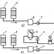
In liquid manometers, the measured pressure or differential pressure is balanced by the hydrostatic pressure of the liquid column. The devices use the principle of communicating vessels, in which the levels of the working fluid coincide when the pressures above them are equal, and when the pressures are equal, they occupy a position where the excess pressure in one of the vessels is balanced by the hydrostatic pressure of the excess liquid column in the other. Most liquid manometers have a visible level of the working fluid, the position of which determines the value of the measured pressure. These devices are used in laboratory practice and in some industries. There is a group liquid differential pressure gauges, in which the level of the working fluid is not directly observed. A change in the latter causes the float to move or a change in the characteristics of another device, providing either a direct indication of the measured value using a reading device, or the transformation and transmission of its value over a distance. Double-tube liquid manometers. To measure pressure and differential pressure, two-pipe pressure gauges and differential pressure gauges with a visible level, often called U-shaped, are used. A schematic diagram of such a pressure gauge is shown in fig. 1, a. Two vertical communicating glass tubes 1, 2 are fixed on a metal or wooden base 3, to which a scale plate 4 is attached. The tubes are filled with working fluid to zero. The measured pressure is supplied to the tube 1, the tube 2 communicates with the atmosphere. When measuring the pressure difference, the measured pressures are supplied to both tubes. Rice. one. Schemes of a two-pipe (c) and one-pipe (b) pressure gauge: 1, 2 - vertical communicating glass tubes; 3 - base; 4 - scale plate Water, mercury, alcohol, transformer oil are used as a working fluid. Thus, in liquid manometers, the function of a sensitive element that perceives changes in the measured value is performed by the working fluid, the output value is the level difference, the input value is pressure or pressure difference. The steepness of the static characteristic depends on the density of the working fluid. To eliminate the influence of capillary forces in manometers, glass tubes with an inner diameter of 8 ... 10 mm are used. If the working fluid is alcohol, then the inner diameter of the tubes can be reduced. Two-pipe water-filled manometers are used to measure pressure, vacuum, differential pressure of air and non-aggressive gases in the range up to ±10 kPa. Filling the pressure gauge with measurement mercury expands the limits to 0.1 MPa, while the measured medium can be water, non-aggressive liquids and gases. When using liquid manometers to measure the pressure difference between media under static pressure up to 5 MPa, additional elements are introduced into the design of the devices to protect the device from one-way static pressure and check the initial position of the working fluid level. The sources of errors in double-pipe pressure gauges are deviations from the calculated values of the local acceleration of free fall, the densities of the working fluid and the medium above it, and errors in reading the heights h1 and h2. The densities of the working fluid and medium are given in tables of thermophysical properties of substances depending on temperature and pressure. The error in reading the difference in the heights of the levels of the working fluid depends on the value of the division of the scale. Without additional optical devices, at a division value of 1 mm, the reading error of the level difference is ±2 mm, taking into account the error in applying the scale. When using additional devices to improve the reading accuracy h1, h2, it is necessary to take into account the difference in the temperature expansion coefficients of the scale, glass and working medium. Single tube pressure gauges. To improve the accuracy of reading the level difference, single-tube (cup) manometers are used (see Fig. 1, b). In a single-tube manometer, one tube is replaced by a wide vessel, into which the greater of the measured pressures is supplied. The tube attached to the scale plate is a measuring tube and communicates with the atmosphere; when measuring the pressure difference, the smaller of the pressures is applied to it. The working fluid is poured into the pressure gauge to the zero mark. Under the action of pressure, part of the working fluid from the wide vessel flows into the measuring tube. Since the volume of liquid displaced from the wide vessel is equal to the volume of liquid entering the measuring tube, Measuring the height of only one column of the working fluid in single-tube manometers leads to a decrease in the reading error, which, taking into account the scale graduation error, does not exceed ± 1 mm at a division value of 1 mm. Other components of the error, due to deviations from the calculated value of the acceleration of free fall, the density of the working fluid and the medium above it, and the thermal expansion of the instrument's elements, are common to all liquid manometers. For double-tube and single-tube pressure gauges, the main error is the error in reading the level difference. With the same absolute error, the reduced error in pressure measurement decreases with an increase in the upper limit of pressure gauge measurement. The minimum measuring range of single-tube water-filled manometers is 1.6 kPa (160 mm w.c.), while the reduced measurement error does not exceed ±1%. The design of pressure gauges depends on the static pressure for which they are designed. Micromanometers. To measure pressure and pressure difference up to 3 kPa (300 kgf / m2), micromanometers are used, which are a type of single-tube manometers and are equipped with special devices either to reduce the scale division value or to increase the accuracy of reading the level height through the use of optical or other devices. The most common laboratory micromanometers are MMN type micromanometers with an inclined measuring tube (Fig. 2). The readings of the micromanometer are determined by the length of the working fluid column n in the measuring tube 1, which has an angle of inclination a.
Rice. 2. : 1 - measuring tube; 2 - vessel; 3 - bracket; 4 - sector On fig. 2 bracket 3 with measuring tube 1 is mounted on sector 4 in one of five fixed positions, which correspond to k = 0.2; 0.3; 0.4; 0.6; 0.8 and five instrument measurement ranges from 0.6 kPa (60 kgf/m2) to 2.4 kPa (240 kgf/m2). The given measurement error does not exceed 0.5%. The minimum division value at k = 0.2 is 2 Pa (0.2 kgf/m2), a further decrease in the division value associated with a decrease in the angle of inclination of the measuring tube is limited by a decrease in the accuracy of reading the position of the working fluid level due to meniscus stretching. More accurate devices are micromanometers of the MM type, called compensation. The error in reading the level height in these devices does not exceed ± 0.05 mm as a result of using optical system to establish the initial level and a micrometer screw to measure the height of the working fluid column, balancing the measured pressure or pressure difference. barometers used to measure atmospheric pressure. The most common are cup barometers filled with mercury, calibrated in mm Hg. Art. (Fig. 3).  Rice. 3.: 1 - vernier; 2 - thermometer The error in reading the height of the column does not exceed 0.1 mm, which is achieved by using the vernier 1, which is aligned with the upper part of the mercury meniscus. For a more accurate measurement of atmospheric pressure, it is necessary to introduce corrections for the deviation of the acceleration of free fall from the normal one and the value of the barometer temperature measured by thermometer 2. If the tube diameter is less than 8 ... 10 mm, capillary depression due to the surface tension of mercury is taken into account. Compression gauges(McLeod pressure gauges), the scheme of which is shown in fig. 4, contain a tank 1 with mercury and a tube 2 immersed in it. The latter communicates with the measuring cylinder 3 and tube 5. The cylinder 3 ends with a deaf measuring capillary 4, a comparison capillary 6 is connected to the tube 5. Both capillaries have the same diameters so that on the measurement results no effect of capillary forces. Pressure is supplied to tank 1 through a three-way valve 7, which during the measurement process can be in the positions indicated in the diagram.  Rice. four. : 1 - reservoir; 2, 5 - tubes; 3 - measuring cylinder; 4 - deaf measuring capillary; 6 - reference capillary; 7 - three-way valve; 8 - the mouth of the balloon The principle of operation of the pressure gauge is based on the use of the Boyle-Mariotte law, according to which, for a fixed mass of gas, the product of volume and pressure at a constant temperature is a constant value. When measuring pressure, the following operations are performed. When valve 7 is set to position a, the measured pressure is supplied to tank 1, tube 5, capillary 6, and mercury is drained into the tank. Then the valve 7 is smoothly transferred to position c. Since atmospheric pressure significantly exceeds the measured p, mercury is displaced into tube 2. When mercury reaches the mouth of cylinder 8, marked in the diagram by the point O, the volume of gas V in cylinder 3 and measuring capillary 4 is cut off from the measured medium. A further increase in the level of mercury compresses the cut-off volume. When the mercury in the measuring capillary reaches the height h and the air inlet into the tank 1 stops and the cock 7 is set to position b. The position of the tap 7 and mercury shown in the diagram corresponds to the moment of taking the pressure gauge readings. The lower measurement limit of compression manometers is 10 -3 Pa (10 -5 mm Hg), the error does not exceed ±1%. The instruments have five measurement ranges and they cover pressures up to 10 3 Pa. The lower the measured pressure, the larger the balloon 1, the maximum volume of which is 1000 cm3, and the minimum volume is 20 cm3, the diameter of the capillaries is 0.5 and 2.5 mm, respectively. The lower measurement limit of the pressure gauge is mainly limited by the error in determining the volume of gas after compression, which depends on the accuracy of the manufacture of capillary tubes. A set of compression pressure gauges, together with a membrane-capacitive pressure gauge, is part of the state special standard for pressure units in the range of 1010 -3 ... 1010 3 Pa. The advantages of the considered liquid pressure gauges and differential pressure gauges are their simplicity and reliability with high measurement accuracy. When working with liquid devices, it is necessary to exclude the possibility of overloads and sudden changes in pressure, since in this case the working fluid may splash out into the line or atmosphere. Principle of operation The principle of operation of the pressure gauge is based on balancing the measured pressure with a force elastic deformation a tubular spring or a more sensitive two-plate membrane, one end of which is sealed in a holder, and the other is connected through a rod to a tribco-sector mechanism that converts the linear movement of an elastic sensing element into a circular movement of the pointer. Varieties The group of devices measuring excess pressure includes: Pressure gauges - devices measuring from 0.06 to 1000 MPa (Measure excess pressure - the positive difference between absolute and barometric pressure) Vacuum gauges - devices measuring vacuum (pressure below atmospheric pressure) (up to minus 100 kPa). Manometers - manometers measuring both excess (from 60 to 240,000 kPa) and vacuum (up to minus 100 kPa) pressure. Pressure gauges - manometers of small overpressures up to 40 kPa Traction gauges - vacuum gauges with a limit of up to minus 40 kPa Traction pressure gauges - pressure and vacuum gauges with extreme limits not exceeding ± 20 kPa Data are given according to GOST 2405-88 Most domestic and imported pressure gauges are manufactured in accordance with generally accepted standards, in this regard, pressure gauges of various brands replace each other. When choosing a pressure gauge, you need to know: the measurement limit, the diameter of the case, the accuracy class of the device. The location and thread of the fitting are also important. These data are the same for all devices manufactured in our country and Europe. There are also pressure gauges that measure absolute pressure, that is, gauge pressure + atmospheric An instrument that measures atmospheric pressure is called a barometer. Gauge types Depending on the design, the sensitivity of the element, there are liquid, deadweight, deformation pressure gauges (with a tubular spring or a membrane). Pressure gauges are divided into accuracy classes: 0.15; 0.25; 0.4; 0.6; 1.0; 1.5; 2.5; 4.0 (the lower the number, the more accurate the instrument). Types of pressure gauges By appointment, pressure gauges can be divided into technical - general technical, electrocontact, special, self-recording, railway, vibration-resistant (glycerin-filled), ship and reference (exemplary). General technical: designed to measure liquids, gases and vapors that are not aggressive to copper alloys. Electrocontact: they have the ability to adjust the measured medium, due to the presence of an electrocontact mechanism. The EKM 1U can be called a particularly popular device of this group, although it has long been discontinued. Special: oxygen - must be degreased, because sometimes even a slight contamination of the mechanism in contact with pure oxygen can lead to an explosion. They are often produced in blue cases with the designation O2 (oxygen) on the dial; acetylene - do not allow copper alloys in the manufacture of the measuring mechanism, since upon contact with acetylene there is a danger of the formation of explosive acetylene copper; ammonia-should be corrosion-resistant. Reference: having a higher accuracy class (0.15; 0.25; 0.4), these devices are used to verify other pressure gauges. Such devices are installed in most cases on deadweight pressure gauges or any other installations capable of developing the required pressure. Ship pressure gauges are designed for operation in the river and sea fleet. Railway: designed for operation on railway transport. Self-recording: pressure gauges in the case, with a mechanism that allows you to reproduce the graph of the pressure gauge on graph paper. thermal conductivity Thermal conduction pressure gauges are based on the decrease in the thermal conductivity of a gas with pressure. These pressure gauges have a built-in filament that heats up when current is passed through it. A thermocouple or resistance temperature sensor (DOTS) can be used to measure the temperature of the filament. This temperature depends on the rate at which the filament gives off heat to the surrounding gas and thus on the thermal conductivity. Often used is the Pirani gauge, which uses a single platinum filament at the same time as heating element and like DOTS. These pressure gauges give accurate readings between 10 and 10−3 mmHg. Art., but they are quite sensitive to chemical composition measured gases. [edit] Two filaments One wire coil is used as a heater, while the other is used to measure temperature through convection. Pirani pressure gauge (one thread) The Pirani pressure gauge consists of a metal wire open to the measured pressure. The wire is heated by the current flowing through it and cooled by the surrounding gas. As the gas pressure decreases, the cooling effect also decreases and the equilibrium temperature of the wire increases. Wire resistance is a function of temperature: by measuring the voltage across the wire and the current flowing through it, the resistance (and thus gas pressure) can be determined. This type of pressure gauge was first designed by Marcello Pirani. Thermocouple and thermistor gauges work in a similar way. The difference is that a thermocouple and a thermistor are used to measure the temperature of the filament. Measuring range: 10−3 - 10 mmHg Art. (roughly 10−1 - 1000 Pa) Ionization manometer Ionization gauges are the most sensitive measuring instruments for very low pressures. They measure pressure indirectly through the measurement of ions formed when the gas is bombarded with electrons. The lower the gas density, the fewer ions will be formed. The calibration of an ion manometer is unstable and depends on the nature of the gases being measured, which is not always known. They can be calibrated by comparison with McLeod pressure gauge readings, which are much more stable and independent of chemistry. Thermoelectrons collide with gas atoms and generate ions. The ions are attracted to an electrode at a suitable voltage, known as a collector. The collector current is proportional to the ionization rate, which is a function of the pressure in the system. Thus, measuring the collector current makes it possible to determine the pressure of the gas. There are several subtypes of ionization gauges. Measuring range: 10−10 - 10−3 mmHg Art. (roughly 10−8 - 10−1 Pa) Most ion gauges fall into two categories: hot cathode and cold cathode. The third type, the rotating rotor pressure gauge, is more sensitive and expensive than the first two and is not discussed here. In the case of a hot cathode, an electrically heated filament creates an electron beam. The electrons pass through the pressure gauge and ionize the gas molecules around them. The resulting ions are collected at the negatively charged electrode. The current depends on the number of ions, which in turn depends on the pressure of the gas. Hot cathode pressure gauges accurately measure pressure in the 10-3 mmHg range. Art. up to 10−10 mm Hg. Art. The principle of the cold cathode gauge is the same, except that the electrons are generated in the discharge by the high voltage electrical discharge created. Cold cathode pressure gauges accurately measure pressure in the 10-2 mmHg range. Art. up to 10−9 mm Hg. Art. Calibration of ionization gauges is very sensitive to structural geometry, gas chemistry, corrosion, and surface deposits. Their calibration may become unusable when turned on at atmospheric and very low pressures. The composition of a vacuum at low pressures is usually unpredictable, so a mass spectrometer must be used simultaneously with an ionization manometer for accurate measurements. hot cathode A Bayard-Alpert hot cathode ionization gauge usually consists of three electrodes operating in triode mode, where the filament is the cathode. The three electrodes are the collector, filament and grid. The collector current is measured in picoamps with an electrometer. The potential difference between the filament and ground is typically 30 volts, while the grid voltage under constant voltage is 180-210 volts, if there is no optional electron bombardment, through heating the grid, which can have a high potential of approximately 565 volts. The most common ion gauge is the Bayard-Alpert hot cathode with a small ion collector inside the grid. A glass casing with an opening to the vacuum may surround the electrodes, but this is usually not used and the pressure gauge is built into the vacuum device directly and the contacts are led out through a ceramic plate in the wall of the vacuum device. Hot cathode ionization gauges can be damaged or lose calibration if they are turned on at atmospheric pressure or even low vacuum. Hot cathode ionization gauges always measure logarithmically. The electrons emitted by the filament move forward and backward several times around the grid until they hit it. During these movements, some of the electrons collide with gas molecules and form electron-ion pairs (electron ionization). The number of such ions is proportional to the density of gas molecules multiplied by the thermionic current, and these ions fly to the collector, forming an ion current. Since the density of the gas molecules is proportional to the pressure, the pressure is estimated through the measurement of the ion current. The low pressure sensitivity of hot cathode gauges is limited by the photoelectric effect. The electrons hitting the grid produce X-rays which produce photoelectric noise in the ion collector. This limits the range of older hot cathode gauges to 10−8 mmHg. Art. and Bayard-Alpert to approximately 10−10 mm Hg. Art. Additional wires at the cathode potential in the line of sight between the ion collector and the grid prevent this effect. In the extraction type, the ions are not attracted by the wire, but by the open cone. Since the ions cannot decide which part of the cone to hit, they pass through the hole and form an ion beam. This ion beam can be transferred to a Faraday cup. |


| Read: |
|---|
Popular:
New
- Abstract: Thermal testing of steam turbines and turbine equipment
- Boric acid technical Reagents
- The ship as a control object The influence of ship vibration on the human body
- Roles in the family Exercise "What children owe us"
- Solving problems on strength of materials
- Acceptance testing of a prototype
- Methods for measuring the flow rate of production wells Determining the error in measuring the mass of liquid
- The best time for shopping: when and what should you buy?
- Greenhouse business: pros and cons
- Alexey Chepa met with Tver bloggers


