Sections of the site
Editor's Choice:
- How to use nitrogen fertilizers
- The size of the trellis for grapes
- Ceramic tiles for fireplaces and stoves: making a choice Types of terracotta tiles for stoves and fireplaces
- Leek planting seedlings in the ground
- Heat-resistant oven tiles
- Sowing leek for seedlings and in open ground: terms and rules for growing
- We are engaged in the construction of a barn for cows and houses for calves How to cover the roof of a cowshed
- What fertilizers are nitrogenous?
- Homemade alcohol stove from aluminum cans Gasoline beer can burner
- Hardening a knife from a bearing, a "peasant" approach
Advertising
| How to convert a welding machine into a power supply. Making an electric welding inverter with your own hands |
Do-it-yourself welding inverter from a computer power supply. Do-it-yourself inverter welding machine circuits from a PC power supplyDo-it-yourself welding inverter from a computer power supply: advantagesA do-it-yourself welding inverter from a computer power supply is becoming more and more popular among both professionals and amateur welders. The advantages of such devices are that they are convenient and lightweight. The use of an inverter power source makes it possible to qualitatively improve the characteristics of the welding arc, reduce the size of the power transformer and thereby lighten the weight of the device, makes it possible to make smoother adjustments and reduce welding spatter. The disadvantage of an inverter-type welding machine is a significantly higher price than that of a transformer counterpart. In order not to overpay large amounts of money for welding in stores, you can make a welding inverter with your own hands. This requires a working computer power supply, several electrical measuring instruments, tools, basic knowledge and practical skills in electrical work. It will also be useful to acquire relevant literature. If you are not confident in your abilities, then you should contact the store for a ready-made welding machine, otherwise, with the slightest mistake during the assembly process, there is a risk of getting an electric shock or burning all the electrical wiring. But if you have experience in assembling circuits, rewinding transformers and creating electrical appliances with your own hands, you can safely proceed with the assembly. The principle of operation of inverter welding The welding inverter consists of a power transformer lowering the mains voltage, stabilizing chokes that reduce current ripple, and an electrical circuit block. For circuits, MOSFET or IGBT transistors can be used. The principle of operation of the inverter is as follows: the alternating current from the network is directed to the rectifier, after which the direct current is converted into alternating current in the power module with increasing frequency. Next, the current enters the high-frequency transformer, and the output from it is the current of the welding arc. Back to index Tools needed to make an inverterTo assemble a welding inverter from a power supply with your own hands, you will need the following tools: 
To create a welding machine from a computer power supply, you need materials to create a printed circuit board, getinaks, spare parts. To reduce the amount of work, it is worth contacting the store for ready-made holders for electrodes. However, you can make them yourself by soldering the crocodiles to the wires of the required diameter. In this work, it is important to observe the polarity. Back to index Welding machine assembly procedureFirst of all, in order to create a welding machine from a computer power supply, you need to remove the power source from the computer case and disassemble it. The main elements that can be used from it are a few spare parts, a fan and standard case plates. Here it is important to take into account the mode of operation of the cooling. It depends on what elements must be added to ensure the necessary ventilation. The operation of a standard fan that will cool the future welding machine from the computer unit must be tested in several modes. Such a check will make sure that the element is working. To prevent the welding machine from overheating during operation, an additional, more powerful cooling source can be installed. To control the required temperature, a thermocouple should be installed. The optimum temperature for the operation of the welding machine should not exceed 72-75°C. But first of all, you should install a handle on the welding machine from a computer power supply of the required size for carrying and ease of use. The handle is mounted on the top panel of the unit with screws. It is important to choose screws that are optimal in length, otherwise too large ones can touch the internal circuit, which is unacceptable. At this stage of work, you should take care of good ventilation of the device. The placement of elements inside the power supply is very dense, therefore, a large number of through holes should be arranged in it in advance. They are carried out with a drill or a screwdriver. Further, to create an inverter circuit, you can use several transformers. Usually choose 3 transformers of type ETD59, E20 and Kx20x10x5. You can find them in almost any electronics store. And if you already have experience in creating transformers yourself, then it is easier to do them yourself, focusing on the number of turns and the performance characteristics of the transformers. Finding such information on the Internet will not be difficult. You may need a current transformer K17x6x5.  It is best to make home-made transformers from getinax coils; an enamel wire with a cross section of 1.5 or 2 mm will serve as a winding. You can use copper sheet 0.3x40 mm, after wrapping it with strong paper. Thermal paper from a cash register (0.05 mm) is suitable, it is durable and does not tear so much. Crimping should be done from wooden blocks, after which the entire structure must be filled with “epoxy” or varnished. When creating a welding machine from a computer block, you can use a transformer from a microwave oven or old monitors, remembering to change the number of turns of the winding. In this work, it will be useful to use electrical literature. As a heatsink, you can use PIV, previously sawn into 3 parts, or other heatsinks from old computers. You can buy them in specialized stores that disassemble and upgrade computers. Such options will pleasantly save time and effort on finding suitable cooling. To create an apparatus from a computer power supply, be sure to use a single-stroke straight-through quasi-bridge, or "oblique bridge". This element is one of the main ones in the operation of the welding machine, therefore it is better not to save on it, but to purchase a new one in the store. Printed circuit boards can be downloaded from the Internet. This will make it much easier to recreate the circuit. In the process of creating the board, you will need capacitors, 12-14 pieces, 0.15 microns, 630 volts. They are necessary to block resonant current surges from the transformer. Also, to make such an apparatus from a computer power supply, you will need capacitors C15 or C16 with the brand K78-2 or SVV-81. Transistors and output diodes should be mounted on heatsinks without additional spacers. In the process of work, it is necessary to constantly use a tester and a multimeter in order to avoid errors and for faster assembly of the circuit.  After manufacturing all the necessary parts, you should place them in the case with their subsequent wiring. The temperature on the thermocouple should be set to 70 ° C: this will protect the entire structure from overheating. After assembly, the welding machine from the computer unit must first be tested. Otherwise, if an error is made during assembly, you can burn all the main elements, or even get an electric shock. On the front side, two contact holders and several current regulators should be installed. The switch of the device in this design will be a standard toggle switch of the computer unit. The body of the finished apparatus after assembly needs to be further strengthened. Back to index Advantages of a welding machine from a computer power supplyA hand-made welding machine will be small and light. It is perfect for home welding, it is convenient to cook on it with two or three electrodes, without experiencing problems with “flashing light” and without fear for the electrical wiring. Power for such a welding machine can be any household outlet, and during operation, such a device will practically not spark.
By making a welding inverter with your own hands, you can significantly save on the purchase of a new device, but this approach will require a significant investment of both effort and time. After assembling the finished sample, you can try to make your own changes to the welding machine from the computer unit and its circuit, to make lightweight models of greater power. And by making such devices for friends on order, you can secure a good additional income. moiinstrumenty.ru Do-it-yourself welding machine from a computer power supplyAs a result of buying a new computer, old power supplies may be left idle, which can be used to create a home workshop. Having spent some effort, you can assemble a welding machine from computer power supplies with your own hands. Such equipment will be useful when performing non-professional tasks of joining metals at home. Financial investments will not be tangible, and the time spent on reworking the power source will fully justify itself with the appearance of a new type of equipment in the arsenal. We will tell you how to do this work with your own hands. Required parts and equipmentWelding inverter machines are complex electronic devices that cannot be assembled independently without certain qualifications and the availability of the necessary equipment. Therefore, you will have to rent expensive equipment for the time of debugging and assembling the unit.
It is extremely important to carry out the installation in strict accordance with the selected scheme, observing the polarity and checking for leaks. Inverter Assembly SequenceWhen preparing for the final assembly of the inverter, it is necessary to take care of the presence of a temperature sensor designed to operate when heated from 70 to 75 ° C. In addition, you need to take care of the sockets for the power cable and the electrode holder with wires with a cross section of 35 mm2, for efficient supply of the welding arc current. Then, having prepared all the necessary elements, we begin the installation in the following sequence:
Self-assembly is a very responsible job, so it is very important to follow the safety rules, both during installation and during the inspection of the assembled inverter. ConclusionYou can assemble an inverter device with your own hands from a computer power supply using additional components that can be found on sale or use used parts. At the same time, you need to make sure that they are working and in accordance with the nominal values. Experienced people are quite capable of the task, and if difficulties arise, it is better to seek advice from professionals. electrod.biz
www.samsvar.ru inverter, spot, microwave and othersThe welding machine is a fairly popular device among both professionals and home craftsmen. But for domestic use, sometimes it makes no sense to buy an expensive unit, since it will be used in rare cases, for example, if you need to weld a pipe or put up a fence. Therefore, it would be wiser to make a welding machine with your own hands, investing a minimum amount of money in it. The main part of any welder operating on the principle of electric arc welding is a transformer. This part can be removed from old, unnecessary household appliances and made into a homemade welding machine. But in most cases, the transformer needs a little refinement. There are several ways to make a welder, which can be both the simplest and more complex, requiring knowledge in radio electronics. microwave welding machineTo make a mini welding machine, you will need a couple of transformers taken from an unnecessary microwave oven. A microwave is easy to find with friends, acquaintances, neighbors, etc. The main thing is that it has a power in the range of 650-800 W, and the transformer in it is working. If the stove has a more powerful transformer, then the device will turn out with higher current rates. So, a transformer removed from a microwave oven has 2 windings: primary (primary) and secondary (secondary).
The secondary has more turns and a smaller wire section. Therefore, in order for the transformer to become suitable for welding, it must be removed and replaced with a conductor with a larger cross-sectional area. To remove this winding from the transformer, it must be cut on both sides of the part with a hacksaw.
This must be done with special care so as not to accidentally touch the primary winding with a saw.
When the coil is cut, its remains will need to be removed from the magnetic circuit. This task will be much easier if you drill the windings to relieve the stress of the metal.
Do the same with the other transformer. As a result, you will get 2 parts with a primary winding of 220 V. Important! Don't forget to remove the current shunts (shown with arrows in the photo below). This will increase the power of the device by 30 percent.
For the manufacture of the secondary, you will need to purchase 11-12 meters of wire. It must be stranded and have a cross section of at least 6 squares.
To make a welding machine, for each transformer you will need to wind 18 turns (6 rows in height and 3 layers in thickness).
Both transformers can be wound with one wire or separately. In the second case, the coils must be connected in series.
The winding should be made very tight so that the wires do not hang out. Next, the primary windings must be connected in parallel.
To connect the parts together, they can be screwed to a small piece of wood board.
If you measure the voltage on the secondary of the transformer, then in this case it will be equal to 31-32 V.
With such a home-made welder, metal 2 mm thick is easily welded with electrodes with a diameter of 2.5 mm.
It should be remembered that cooking with such a home-made apparatus should be done with breaks for rest, since its windings are very hot. On average, after each used electrode, the device should cool down for 20-30 minutes. Thin metal with a unit made from a microwave will not be able to cook, as it will cut it. To adjust the current, a ballast resistor or choke can be connected to the welder. The role of a resistor can be performed by a piece of steel wire of a certain length (selected experimentally), which is connected to a low-voltage winding. AC WelderThis is the most common type of apparatus for welding metals. It is easy to make at home, and it is unpretentious in operation. But the main drawback of the device is the large mass of the step-down transformer, which is the basis of the unit.
For home use, it is enough that the device produces a voltage of 60 V and can provide a current of 120-160 A. Therefore, for the primary, to which the 220 V household network is connected, a wire with a cross section of 3 mm2 to 4 mm2 is required. But the ideal option is a conductor with a cross section of 7 mm2. With such a cross section, voltage drops and possible additional loads will not be terrible for the device. From this it follows that for the secondary you need a conductor having a diameter of 3 mm. If we take an aluminum conductor, then the calculated cross section of the copper is multiplied by a factor of 1.6. For the secondary, you will need a copper bus with a cross section of at least 25 mm2 It is very important that the winding conductor is covered with rag insulation, since the traditional PVC sheath will melt when heated, which can cause an interturn short circuit. If you have not found a wire with the required cross section, then you can make it yourself from several thinner conductors. But at the same time, the thickness of the wire and, accordingly, the dimensions of the unit will increase significantly. First of all, the base of the transformer is made - the core. It is made of metal plates (transformer steel). These plates should have a thickness of 0.35-0.55 mm. The studs connecting the plates must be well insulated from them. Before assembling the core, its dimensions are calculated, that is, the dimensions of the “window” and the cross-sectional area of the core, the so-called “core”. To calculate the area, use the formula: S cm2 \u003d a x b (see figure below).
But it is known from practice that if a core with an area of less than 30 cm2 is made, then it will be difficult to obtain a high-quality seam with such an apparatus due to a lack of power reserve. Yes, and it will heat up very quickly. Therefore, the cross section of the core must be at least 50 cm2. Despite the fact that the mass of the unit will increase, it will become more reliable. To assemble the core, it is better to use L-shaped plates and place them as shown in the following figure until the thickness of the part reaches the required value.
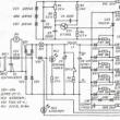
At the end of the assembly, the plates must be fastened (at the corners) with bolts, then cleaned with a file and insulated with fabric insulation. Now you can start winding the transformer.  One caveat should be taken into account: the ratio of turns on the core should be 40% to 60%. This means that on the side where the primary is located, there should be fewer turns of the secondary. Due to this, at the start of welding, the winding with more turns will be partially switched off due to the occurrence of eddy currents. This will increase the current strength, which will positively affect the quality of the seam. When the winding of the transformer is completed, the network cable is connected to the common wire and to the 215 turn branch. Welding cables are connected to the secondary winding. After that, the contact welding machine is ready for operation. DC deviceTo cook cast iron or stainless steel, a DC apparatus is required. It can be made from a conventional transformer unit if a rectifier is connected to its secondary winding. Below is a diagram of a welding machine with a diode bridge.  Scheme of a welding machine with a diode bridge The rectifier is assembled on D161 diodes, capable of withstanding 200A. They must be installed on radiators. Also, to equalize the current ripple, you will need 2 capacitors (C1 and C2) for 50 V and 1500 uF. This circuit also has a current regulator, the role of which is performed by the inductor L1. Welding cables are connected to contacts X5 and X4 (direct or reverse polarity), depending on the thickness of the metal to be joined. Computer power supply inverterIt is impossible to make a welding machine from a computer power supply. But it is quite possible to use its case and some parts, as well as the fan. So, if you make an inverter with your own hands, then it can easily be placed in the PSU case from the computer. All transistors (IRG4PC50U) and diodes (KD2997A) must be installed on radiators without the use of gaskets. To cool the parts, it is advisable to use a powerful fan, such as Thermaltake A2016. Despite its small size (80 x 80 mm), the cooler is capable of 4800 rpm. The fan also has a built-in speed controller. The latter are regulated using a thermocouple, which must be mounted on a radiator with installed diodes. Advice! It is recommended to drill several additional holes in the PSU case for better ventilation and heat dissipation. The overheating protection installed on the radiators of the transistors is set to operate at a temperature of 70-72 degrees. Below is a circuit diagram of a welding inverter (in high resolution), according to which you can make a device that fits in the PSU case.
The following photos show what components a homemade inverter welding machine consists of, and how it looks after assembly.
electric motor welderTo make a simple welding machine from the stator of an electric motor, it is necessary to select the motor itself that meets certain requirements, namely, that its power is from 7 to 15 kW. Advice! It is best to use a 2A series motor, as it will have a large magnetic circuit window. You can get the right stator in places where scrap metal is accepted. As a rule, it will be cleaned of wires and after a couple of blows with a sledgehammer it will split. But if the case is made of aluminum, then in order to remove the magnetic circuit from it, it will be necessary to anneal the stator. Preparation for workPlace the stator with the hole up and place bricks under the part. Next, stack the wood inside and set it on fire. After a couple of hours of roasting, the magnetic core will easily separate from the body. If there are wires in the housing, they can also be removed from the grooves after heat treatment. As a result, you will receive a magnetic circuit cleaned of unnecessary elements.
This blank should be well impregnated with oil varnish and allowed to dry. You can use a heat gun to speed up the process. Impregnation with varnish is done so that after removing the screeds, the package does not spill. When the blank is completely dry, using a grinder, remove the ties located on it. If the ties are not removed, they will act as short-circuited turns and take power from the transformer, as well as cause it to heat up. After cleaning the magnetic circuit from unnecessary parts, it will be necessary to make two end caps (see the figure below).
The material for their manufacture can be either cardboard or pressboard. You also need to make two sleeves from these materials. One will be internal, and the second - external. Next, you need:
Transformer manufacturingAfter carrying out the above steps, it will be possible to make a welding transformer from the magnetic circuit. For these purposes, you will need a wire covered with fabric or glass-enamel insulation. To wind the primary winding, you need a wire with a diameter of 2-2.5 mm. The secondary winding will require about 60 meters of copper bus (8 x 4 mm). So, the calculations are done as follows.
For the primary winding, a conductor with a diameter of 2.36 mm is suitable, which needs to be folded in half. In principle, you can take any wire with a diameter of 1.5-2.5 mm. But first you need to calculate the cross section of the conductors in the coil. First you need to wind the primary winding (at 220 V), and then the secondary. Its wire must be insulated along its entire length. If you make a tap in the secondary winding in the area where 13 V is obtained and put a diode bridge, then this transformer can be used instead of the battery if you want to start the car. For welding, the voltage on the secondary winding should be in the range of 60-70 V, which will allow the use of electrodes with a diameter of 3 to 5 mm. If you have laid both windings, and there is free space in this design, then you can add 4 turns of a copper bus bar (40 x 5 mm). In this case, you will receive a winding for spot welding, which will allow you to connect sheet metal up to 1.5 mm thick. It is not recommended to use metal for the manufacture of the case. It is better to make it from textolite or plastic. In places where the coil is attached to the body, rubber gaskets should be laid to reduce vibration and better insulation from conductive materials.
Homemade spot welding machineThe finished spot welding machine has a rather high price, which does not justify its internal “stuffing”. It is arranged very simply, and it will not be difficult to make it yourself.
To independently manufacture a spot welding machine, you will need one transformer from a microwave oven with a power of 700-800 watts. It is necessary to remove the secondary winding from it in the manner described above, in the section where the manufacture of a microwave welding machine was considered. The spot welding machine is made in the following way.
In this case, the result was positive. Therefore, the creation of a spot welding machine can be considered completed. technika.expert The easiest do-it-yourself welding inverter from available partsDo-it-yourself welding inverter was assembled by hundreds of craftsmen. As practice shows, there is nothing super complicated in this process. If you have experience and desire, you can acquire the necessary details and spend some time working.  For the manufacture of the device, it is necessary to stock up with all the necessary parts and accessories. The transformer-type welding machine was so bulky and problematic in operation that the thyristor-based inverters that replaced it quickly gained general popularity. Further development of manufacturing technologies for semiconductor components made it possible to create powerful field-effect transistors. With their advent, inverters have become even lighter and more compact. Improved conditions for adjusting and stabilizing the welding current make it easy to work even for beginners. Inverter design selection As a case, you can use an old computer unit. The layout of a homemade welding inverter is unoriginal and similar to most other designs. Most parts can be replaced with analogues. It is necessary to determine the dimensions of the device and start manufacturing the case if all the main elements are present. You can use ready-made heatsinks (from old computer power supplies or other devices). In the presence of an aluminum bus with a thickness of 2-4 mm and a width of more than 30 mm, they can be made independently. You can use any fan from old devices. All dimensional parts must be placed on a flat surface, view the connection possibilities according to the schematic diagram. Then determine the installation location of the fan so that hot air from some parts does not heat others. In a difficult situation, two exhaust fans can be used. The cost of coolers is small, the weight is also insignificant, the reliability of the entire device will increase significantly. The largest and heaviest parts are a transformer and a choke to smooth out ripples. It is desirable to place them in the center or symmetrically along the edges so that their weight does not pull the device in one direction. Working with a device worn on the shoulder and constantly sliding to one side during welding is extremely inconvenient. With a satisfactory arrangement of all parts, it is necessary to determine the dimensions of the bottom of the device and cut it out of the available material. The material must be non-conductive, usually getinax, fiberglass. In the absence of these materials, wood treated with fire retardant and moisture protection agents can be used. The latter option has some advantages. Screws can be used to fasten parts, rather than threaded connections. This will somewhat simplify and reduce the cost of the manufacturing process. Electrical diagram of the inverterAll inverters have a similar block diagram: 
The scheme chosen for home-made manufacturing is arranged according to the classical method. The heart of the circuit is the oblique bridge, which provides the best performance at maximum simplicity and cost. The power circuit is controlled by the TL494 controller. Control functions and adjustment of the welding current are carried out by the PIC16F628 microcontroller. Protection of the device from overheating is also implemented through it. Depending on the maximum current and the parts used, several firmware versions of the device are possible with different maximum allowable welding current. The power supply for the logic elements of the circuit and low-voltage equipment is based on the TNY264 PWM controller. The schematic diagram, despite the large number of elements, is made quite simply. The entire control system is made on several boards:
Rectifier diodes with protective circuits, power transistors, transformer, measuring resistance are installed on the board of power elements. The required version of the board must be selected according to the available components for the welding inverter.  The inverter machine requires a power control board. On the rectifier board, bridge elements, smoothing capacitors, soft start relays, resistances that compensate for changes in parameters due to temperature (thermistors) are installed. The following circuits are located on the power control boards:
Before assembling the boards, the tracks for installing power elements must be reinforced with copper wire with a cross section of 2.5-4 mm. For tinning the tracks, it is advisable to use refractory solder. Transformer and choke for inverterIn the manufacture of a core for a welding inverter transformer, you can use horizontal transformers from old TVs. You will need six transformers of the TVS110PTs15.U type. The tightening bracket must be removed from the transformers (unscrew the two M3 nuts and remove the bracket). The winding can be sawn on both sides with a hacksaw or grinder, observing the necessary precautions. If, after removing the winding, the core does not separate into two parts, you need to clamp it in a vise and separate it with a light blow. The surfaces of the parts must be cleaned of epoxy. After preparing the magnetic cores, you need to make a frame. The optimal material for the frame will be fiberglass with a thickness of 1-2 mm, but you can use getinax or cardboard. Technical characteristics of the assembled magnetic core: Transformers can be borrowed from an old TV.
The cross section and number of turns of the windings must be calculated based on the maximum allowable operating current for the device. Windings must be placed across the entire width of the window to reduce overhead. As a material for windings, you can use copper foil or litz wire of the desired section to eliminate the skin effect. The insulating material between the layers and windings can be wax paper, varnished cloth, FUM tape. If it is necessary to control the welding current, a current transformer can be made. For its manufacture, you will need two rings of the K30x18x7 type. They need to be wound with 85 turns of copper wire in varnish insulation with a cross section of 0.2-0.5 mm. The ring is put on any of the output wires of the device. Using an inverter in a three-phase networkSometimes when the network is overloaded, there is not enough power for the normal operation of the inverter. If possible, a single-phase inverter can be converted to a three-phase one. When connected to a single-phase network (the plug is plugged into a socket), the K1 starter is turned on. One pair of its contacts connects the wires coming from the plug to the regular switch (on / off) of the inverter. Another pair will connect the tracks cut on the board from the switch to the stationary rectifier.
Starter K1 must have contacts with a maximum allowable current of at least 25 A. To connect the voltage from a three-phase rectifier, a K2 starter is used. The maximum allowable current of its contacts must be at least 10A. To connect to a three-phase network, it is advisable to use a 3p + N + E socket (three phase wires, zero and ground). The device can be built into the inverter or made as a separate unit. Production in the form of a separate block is optimal when working in one place. With frequent movements, carrying two devices is not convenient. Conclusion on the topicMaking a welding inverter with your own hands is not so difficult. With a lack of experience, you can always consult with specialists. The result is an excellent device with additional features not found in industrial inverters.
Repairing a do-it-yourself device will not create any special problems, and using the tool in your work will be a pleasure. A home-made welding machine, when properly assembled, will do its job no worse than a factory-made unit. A welding machine is a technical device designed to connect various types of parts by heating them. Existing schemes allow you to assemble devices even from old computer units and TVs. But it is recommended to start such work if you have at least basic skills in working with electrical appliances. Preparing to assemble the device from a computer power supplyA simple and highly efficient welding machine can be assembled from an old computer power supply. To assemble such a homemade device, you will need the following:
In the process of assembling the welding machine, a multimer will be needed.
Such a home-made device will be assembled using a case and some parts of a computer power supply. Cooling is very important. Test the fan in several modes. It must be of sufficient power. A thermocouple must be installed. The most convenient handle for the operator is fixed on the upper end of the power supply. Use screws of sufficient length for fastening. It is important that they do not reach the internal circuit. Drill a few additional holes in the case for better cooling of the machine. The quality of ventilation directly affects how long the future welding machine can work.
Figure 1. Transformer diagram. The scheme involves the use of transformers in the amount of three pieces. The transformer diagram can be found in Figure 1. Transformers of the ETD 59, E20 and Kx20x10x5 series are suitable. You can wind them with your own hands. Additionally, you will need a current transformer. A product of the K17x6x5 series is usually used. For self-manufacturing of the transformer, use a new enamel wire f1.5 or f2. Winding on getinax coils, crimping with wooden pads, impregnation with epoxy resin is carried out. A microwave oven transformer is also suitable, but you need to reduce the number of turns of the secondary winding. This requires an additional calculation beforehand. This is a more economical option, but it requires significantly more effort and time. In practice, it is much easier to buy a ready-made transformer. Step-by-step instructions for assembling the welding unit
A circuit based on a computer power supply has been tested by more than a dozen welders. Such home-made welding machines require the replacement of 15tb60 diodes with 25tv60 diodes. In practice, it has been found that this improves the performance of the unit. Diodes 150ebu02 must be installed in 2. For additional savings, you can cut the PIV into 3 parts and use this design instead of a radiator. The design necessarily includes a forward single-cycle quasi-bridge converter. He is the "oblique bridge". It is recommended not to save on this element. It is better to buy a new high quality part. In the process, you will need a tester and a multimeter. They will allow you to assemble the scheme as accurately as possible and in the shortest possible time. A home-made device can be connected to the network only after preliminary testing. Output diodes and transistors are mounted on heatsinks without additional spacers. The overheating protection must be set to 70 degrees. You can do this with a thermocouple. After connecting all the parts into one structure, place them inside the case and make the correct wiring. The toggle switch for turning on the block will act as a switch for the future welding unit. Contact holders and a current regulator should be placed on the front panel. The body must be fixed as firmly and carefully as possible. The manufacture of such a welding machine does not need a lot of money, but it takes time and effort. If you wish and have the necessary skills, you can make individual changes to the circuit and get a welding machine with the characteristics you need. Homemade apparatus for resistance welding
Figure 2. Scheme of the electronic unit for contact welding. A welding machine of this kind will help you connect a wide variety of metal products. A current passes through the junction, which leads to its deformation. There are spot, butt and seam methods of such welding. Before starting the manufacture of such a unit, select the type that suits you best. The "contact" welding machine can be made stationary, suspended and mobile. Most often, such units are used for welding wires and various pipes. But you can adapt it to connect almost any product. The diagram of the electronic unit of such a device is shown in Figure 2. Consider the fact that during operation such a welding machine consumes a lot of electricity. It can be used to weld parts with a thickness of 0.09-0.9mm. It consists of 2 main elements: a power supply unit, which includes a transformer and a relay, and a gun. An electrode is connected to the first winding by means of a cable. The second output during welding must be connected to the workpiece to be welded. The gun for welding consists of 2 elements of the same size and shape. You can use getinaks, textolite and other insulators. To assemble such a welding machine, you will need:
Attached to the front is a small switch, lamp holder and adapter. Behind you need to place the backlight switch. The lining is connected with screws. The welding cable is connected to the adapter. During the assembly process, you need to take into account the dimensions of the selected power supply and transformer. An important characteristic of the transformer is the cross section of the magnetic circuit. It must exceed 60 cm². The primary winding is made for 160-165 turns. It must be placed on one side of the magnetic circuit. The insulation is done with wooden wedges. A bend must be created on the secondary winding. This is done with loops. The bend will make it possible to fix the welding cable with the help of special bolts. The layers of the primary winding are insulated with PTFE or electrical tape. Tape is used for fixation. The magnetic circuit must be tightened with corners and M8 bolts. A screed is made to straighten the plate. The frame is fixed with wooden wedges. After that, you need to check the operation of the transformer. Connect it to a 220 V household power supply and at the same time measure the voltage on the second winding. It should be 41 V. The auxiliary transformer will provide a voltage of 6-15 V on the second winding. For its manufacture, a magnetic circuit of 1 cm² is used. The windings between the magnetic core must be insulated with tape. A complete do-it-yourself inverter welding machine
Figure 3. Schematic diagram of the welding inverter. The design features of the welding inverter can significantly reduce the size and weight of this unit. There are many models available on the market with different characteristics that allow you to perform a wide range of tasks. But if you don’t want to spend money on buying a finished unit, you can assemble it yourself. It is only necessary to understand the features of functioning and the principle of operation of the main internal circuits and elements. The circuit diagram of a standard inverter can be found in Figure 3. The welding inverter is assembled from a number of elements, including a power supply, a power unit and power switch drivers. This example describes step by step the manufacture of a homemade inverter with characteristics such as:
To equalize the voltage, you need to wind the width of the frame. In the sum of the windings there will be 4:
The bar with the power supply is fixed separately. It is separated from the power part by means of a metal sheet. The sheet itself is electrically connected to the welding body. The gate drive conductors are soldered as close as possible to the transistors. Between themselves, they twist in pairs. The cross section does not play a special role, but it is important that the length of the conductors be no more than 15 cm. The functions of the power supply unit are performed by an ordinary flyback. The shielding winding must cover the primary winding of the unit. Primary turns must be fully covered by superimposed turns. Also, they must have the same direction. Between them, insulation is made of varnished cloth or masking tape. The final stage of the inverter assemblyIt is important to correctly configure the power supply. You must choose such a resistance at which the voltage to supply the relay would be 20-25 V. Make input rectifiers using powerful high-quality radiator elements. For this task, you can use models from old computers from the Pentium 4 era. On the radio market, you can buy the necessary parts for a few dollars. A thermal sensor must be installed in the interior of the housing. This element will heat up the most. The control unit itself must be equipped with a TL494 PWM controller. It works with one control channel and is responsible for stabilizing the current in the arc. The PWM voltage is controlled by capacitor C1. Together, these elements affect the amount of welding current. This is just one of the many options available. If necessary, and if you have the appropriate knowledge, you can make your own adjustments.
Thus, in the self-assembly of the welding machine there are no super-complicated steps. Even an old computer power supply or a microwave oven can be adapted for this. You just need to do everything according to the instructions, clearly following each step of the guide. Successful work! To perform welding work at home, an inverter welding machine is indispensable. The principle of its operation is based on the use of transistors and switches, with the help of which the mains voltage is first transformed into a constant one. Then the characteristics of the current change (the frequency of the sinusoid increases). These actions lead to a decrease in the voltage value, which leads to a rectification of the current, while the frequency of the current does not change. The widespread use of these devices is associated with a number of its advantages, which include:
The disadvantages of a welding inverter, which is made independently, are:
It should be noted that self-assembly of the inverter is quite painstaking work., which takes a lot of time and requires certain skills. But modern manufacturers offer a wide selection of components, which greatly facilitates their choice. The selection of parts itself is based on the compatibility of parameters by type and characteristic, as well as on the possibility of simple replacement in the future. The main elements of the inverter are:
Basic output features include:
Preparatory stageBefore you start buying parts for the manufacture of an inverter, you must accurately represent the values of the output parameters, as well as have electrical circuits of all elements (general circuit, power supply). Consider the manufacture of a welding machine with input characteristics:
The output will be a current converted to a value of 250 A, that is, it has increased its input value by 8 times. With this machine, you can make a weld by placing the electrode less than 1 cm to the workpiece to be welded. Before proceeding with the assembly of the device, it is necessary to prepare the following materials and tools:
After completing the preparatory work, you can proceed with the assembly. 
Inverter power supplyThe board where the inverter power supply is located is assembled separately from the power element of the device. In addition, they need to be separated from each other by a sheet of metal, which is rigidly fixed to the body. The main element of the power supply is a transformer, which can be made independently. With its help, the voltage that comes from the network will be converted to a safe value for life, and then increase the current strength to perform welding. The core material can be 7x7 or 8x8 iron. In this case, you can take it as standard plates or cut off the required piece of metal from an existing sheet. The winding is carried out with a copper wire of the PEV brand, since it is this material that provides the required characteristics to the maximum (small cross section with sufficient width). The use of a different material as a winding may significantly affect the characteristics of the transformer, for example, increase the heating of this part. The assembly of a transformer consisting of 2 windings begins with the creation of a primary winding. To do this, a wire with a cross section of 0.3 mm is wrapped 100 times on the core. It is important that the winding occupies the entire width of the core. This feature will improve the operation of the inverter during mains voltage fluctuations in the process of further operation. In this case, each turn should fit snugly against the previous one, while overlap should be avoided. After all 100 turns have been completed, a layer of special insulating paper or fiberglass cloth must be laid. Please note that the paper will darken during operation. Next, the secondary winding is performed. To do this, you need to take a copper wire with a cross section of 1 mm and make 15 turns, trying to distribute them over the entire width, at an equal distance from each other. After coating them with varnish and drying, they wind the 2nd layer with a copper wire with a cross section of 0.2 mm, also making 15 turns. They also need to be distributed, as in the previous case, and isolated. The last layer for the secondary winding will be a PEV with a cross section of 0.35 mm, while there will be 20 turns. The last layer must also be insulated.  FrameNext, proceed to the manufacture of the case. Its size should be commensurate with the dimensions of the transformer and plus 70% for the placement of the remaining parts of the inverter. The body itself can be made of sheet steel with a thickness of 0.5-1 mm. To connect the corners, you can use bolts or use special bending machines to bend the sheet to the desired size. If you place a handle on the case for attaching the inverter to a belt or for ease of carrying, this will greatly facilitate the operation of the device in the future. In addition, the design of the case should provide for fairly easy access to all parts located inside it. It is necessary to make several technological holes on it for switches, a power button, a light signaling of health, as well as cable connectors. 
Power section and inverter unitThe power unit for the inverter is a transformer, a feature of which is the presence of 2 cores, which are located next to a small gap, laying a sheet of paper. This transformer is assembled similarly to the previous one. An important detail is that the insulating layer between the turns of the wire must be strengthened, which will prevent voltage breakdown. In addition, gaskets made of PTFE are laid between the layers of wires. Capacitors that are connected according to the diagram can be attributed to the power part. They are designed to reduce the resonance of transformers, and are also designed to minimize and compensate for current losses in transistors. The inverter unit of the device is used to convert current, which increases the output frequency. For this, transistors or diodes are used in the inverter. If it is decided to use diodes in this block, then they must be assembled into an oblique bridge according to a special scheme. The outputs from it go to transistors, which are designed to return alternating current at a higher frequency. The diode bridge and transistors must be separated by a partition.  Cooling systemSince all elements of the unit are subject to heat, it is necessary to organize a cooling system that will ensure uninterrupted reliable operation. To do this, you can use coolers from computers, as well as make several additional holes in the case for easy air access into the device. However, there should not be too many such holes to avoid getting excess dust into the case. Coolers should be located in such a way that they can work to remove air from the device case. Cooling elements need maintenance, such as replacing thermal paste, so access to them should be easy. There are several parts in the inverter that require mandatory cooling. These are transformers. For their cooling it is reasonable to mount 2 fans. In addition, the diode bridge needs additional cooling. It is mounted on a radiator. Installing such an element as a temperature sensor, and its further connection to the LED on the case, will allow you to give a signal when an unacceptable temperature is reached and turn off the inverter from the power supply for cooling.  AssemblyThe inverter is assembled in the following order:
When everything is installed, you can check the operation of the device. Checking workTo check the device, you must use an oscilloscope for this. The inverter is connected to a 220 V network, and then the device checks how the output parameters correspond to the required ones. For example, the voltage should be in the range of 500-550 V. With absolutely correct assembly and correctly selected parts, this value should not cross the threshold of 350 V. After such measurements and acceptable indicators of the oscilloscope, you can begin to weld. After the first electrode is completely burnt out, it is necessary to measure the temperature on the transformer. If it boils, then the circuit needs to be finalized, the device must be turned off and changes made. Only after measures have been taken to eliminate this defect, it is possible to restart with the same temperature measurement after the end of work. 
Operating rulesThe welding inverter can be used both for welding parts made of ferrous metal, and for working with non-ferrous. It is useful both in a private house, in the country, and in the garage. During its operation, it is necessary to monitor the quality of voltage and frequency in the network. For long-term use of this unit, it is necessary to periodically check the performance of its individual cleaning, carry out preventive measures to clean it from dust and dirt.
When making an inverter yourself, you must:
Title: We make a welding machine from a computer power supply Publisher: Praktik-Tsentr Year: 2009 Pages: 11 Language: Russian Format: pdf Quality: excellent Size: 4.98Mb This small brochure provides an example of how, based on an AT computer power supply, you can make a small and lightweight machine for small welding jobs that do not require high current, which can be plugged into almost any outlet without fear for the safety of the wiring. In the amateur radio environment, the odiotaktiy forward quasi-bridge converter, and in common parlance the "oblique" bridge, has become the main type of converter for building welding current sources. However, many industrial welding inverters, up to a load current of 250A (for example, liSAB Caddy Professional 250), use this circuitry. This paper presents an attempt to make a small-sized and lightweight device for small welding jobs that do not require high current, which can be plugged into almost any outlet without fear for the safety of the wiring. The entire welder fit in a case from an AT computer power supply, a PIV radiator, sawn into 3 parts, was used as coolers, IRG4PC50U transistors were installed on two smaller parts, and KD2997A output diodes were installed on the larger one. Transistors and output diodes are mounted on heatsinks without gaskets! Everything is blown by a rather powerful Thermaltake A2016, 80x80mm, 0.48A, 4800rpm fan, the fan has a built-in speed control depending on temperature, a thermocouple sensor mounted on the output diode heatsink. It was also necessary to drill additional holes in the case for better cooling, since the mounting turned out to be quite tight and the existing holes on the front of the case were not enough. Overheating protection works at about 70-72 degrees on the radiators of transistors. Despite the small size and weight of the PB, it turned out to be quite decent, it seems to me worthy, about 100% at currents up to 80A, and at 100A you can already tolerably cook in threes ... delayuvsesam.ru Most welding machines have inverter circuits, where field-effect transistors are used as power switches. This scheme allows to reduce the weight and dimensions of the installation. Today, using a wide range, you can buy a welding machine in the store, but it will most likely have a principle of operation that is similar to that of the rest. In order to make a welding inverter on your own, as well as if it is necessary to repair it, you should familiarize yourself with its device. Characteristics of the future welding inverterThe installation must include some elements, among them:
The welding inverter, the self-production of which will be described below, will have the following characteristics:
Using such an installation, it will be possible to work with an electrode whose diameter is 5 mm, while the arc length can reach 1 cm. The performance of the device will not be inferior to those that can be purchased in a store. Manufacturing technology of the welding inverterFigure 1. Scheme of the inverter power supply. On fig. 1 contains a diagram of the power supply unit of the installation, which should help the craftsmen who intend to carry out the work on their own. In order to achieve a balancing of the voltage indicator, windings should be made to the width of the frame. In general, their number should be limited to four:
It is recommended to install the board on which the power supply will be mounted separately. It is separated from the power component by a steel sheet, which is attached to the body. Conductors that have a goal of driving gates should be soldered as close as possible to the transistors, they will have to be twisted together so that they form pairs. The cross section is not critical, but the length of the conductors should not be given an indicator of more than 150 mm. When making inverters with your own hands, you should use diagrams. One of them, with the image of the power part, is contained in Fig. 2. The block (Fig. 3) in such an installation is represented by an ordinary flyback. The primary of the transformer unit should be protected by a shielding winding made from the same wire. Figure 2. Scheme of the power part of the inverter. In this case, the laid turns must completely cover the primary, and their direction must coincide. In the space between them, insulation from masking tape should be laid, the last of which can be replaced with varnished cloth. To equip the power supply, it is necessary to select the resistance so that the voltage supplied to the power supply of the relay is equivalent to an indicator in the range from 20 to 25 V. The diagram above shows all the characteristics of the power section. The most priority for input rectifiers is to select high-quality radiator components. Those that were mounted in old computers that functioned on the basis of Pentium 4 or Alton 64 processors are perfect. You can buy them on the secondary market for a symbolic cost. The control circuits of the described installations have a thermal sensor in a single copy. It should be located in the inner space of the radiator housing, the heating temperature of which is the highest. In order to make a control unit, you should purchase a PWM controller. It works only from one control channel, through which the current in the arc is adjusted. The welding inverter circuit allows you to determine the location of the capacitor C1, which will determine the PWM voltage, the current value during welding depends on the last characteristic. Tools and materialsFigure 3. Scheme of the inverter power supply. To carry out the manufacturing process of welding inverters with your own hands, you have to prepare:
Depending on the scheme that will be used in the work, you can use other components for the work. Alternative inverter manufacturing optionTo make a welding inverter with your own hands, you need to use a copper strip of 40 mm, the thickness of which is 0.3 mm, with which you should wind it. In the role of a thermal layer, it is necessary to use paper from a cash register. You can use another one that has similar characteristics, as the only requirement for this component of the winding is the strength of the material. It is worth considering that during the operation of the device, the paper will darken, but this will not affect its technical and strength characteristics in any way. Winding with a thick wire cannot be done, despite the fact that some craftsmen do just that. https://moyasvarka.ru/www.youtube.com/watch?v=LvIyLUOzS64 This requirement is due to the fact that this can act as a cause of transformer overheating. The secondary can be equipped with 3 strips of copper, which can be separated with a fluoroplastic layer. In this case, high-quality durable paper is also used. Welding inverter transformers are supplemented with fans, since the winding will heat up in any case. It is permissible to use a cooler from a 220 V system unit. It will be enough to supply the inverter with 6 fans, half of which should be directed directly to the motor winding. It is unacceptable to forget about the air intakes, it is necessary to mount them opposite the fans, this will eliminate the obstacle to the intake in the right amount. Scheme of a welding transformer. Next, the design of the inverter must be equipped with a power oblique bridge on two radiators. In this case, the upper part should be located at one end, while the lower part can be reinforced with a mica gasket on the remaining bridge. The leads of the diodes must be positioned towards the transistors. The board must contain 14 capacitors of 0.15 microns and 630 V, their presence is necessary to reduce resonant emissions. To ensure the lowest IGBT losses, snubbers should be mounted in a chain, which will be supplied with capacitors. It is recommended to use only high-quality devices, with regard to even the simplest inverter. As an optimal option, you can use the model SVV81. Although the IGBT opens in a shorter time, the reverse process involves a much longer period. Even if you use welding inverter circuits during manufacturing and do the work correctly, this does not mean that you can easily set up the machine at the last stage. Initially, you have to supply power to the PWM, the mark should correspond to 15 V, along with this, you have to apply a discharge to the cooler, this will allow you to start the cooling system, and you need to analyze the synchronism. It is necessary to check whether the function of the inverter resistor closing relay has started, which will happen after a maximum of 8 seconds of connecting the PWM board. https://moyasvarka.ru/www.youtube.com/watch?v=Bf_4AbNBF7M The board must also be checked, rectangular pulses should be identified after the relay trips. Then power is supplied to the bridge, which will make sure that it is working, while it is worth setting the idle. Do-it-yourself welding inverter can be made using different schemes, instructions and drawings, but it is worth checking whether the transformer phases are installed correctly. This can be done using beam oscilloscopes. The first beam must be thrown on the primary winding, the other on the secondary. In this case, the voltage should not jump more than 330 V at the lower emitter. In order to determine the operating frequency of the device, the PWM frequency should be lowered until a bend appears on the lower IGBT. The resulting value should be noted, after which the number will be divided by 2, add the frequency of supersaturation. https://moyasvarka.ru/www.youtube.com/watch?v=dKRTeptgkYg The test power supply to the bridge should be carried out using any household appliance, 2200 W is recommended. An electric kettle will be the most suitable option for the device. It is important to remember that the driver bridges should be placed under the heatsink above the IGBT, but should not be placed closer than 3 cm to the resistors. The conductors connecting optocouplers and PWM are not recommended to be located near the source of interference, they must be short. moyasvarka.ru Do-it-yourself welding inverter manufacturing technology
In any specialized store selling electrodes and welding equipment, you can find a welding inverter. You can get it at a fairly high price, but if you have basic knowledge in electronics and know how to handle a soldering iron, you can assemble a welding inverter with your own hands, which will not be inferior to the factory counterpart.  Scheme of the device of the welding inverter. Initially, you should familiarize yourself with all the main nuances and aspects of this case: diagrams, drawings, instructions and the assembly process itself. Homemade welding inverterA home-made welding inverter is designed for long-term operation, it can work with electrodes with a diameter of up to 4 mm. Among its advantages, a large current reserve can be noted. The circuit of such a device is a single-cycle inverter that runs on processor control and uses digital induction. The characteristics of the inverter are shown below:
Among its functionalities are: Scheme of operation of the welding inverter.
The scheme of this welding inverter consists of three main blocks:
To independently create an inverter and fully implement the circuit, you will need to purchase microcontrollers and other boards that will be required to assemble it. The diagram of the power section is shown in Figure 1. A do-it-yourself welding inverter from a computer power supply is becoming more and more popular among both professionals and amateur welders. The advantages of such devices are that they are convenient and lightweight. The use of an inverter power source makes it possible to qualitatively improve the characteristics of the welding arc, reduce the size of the power transformer and thereby lighten the weight of the device, makes it possible to make smoother adjustments and reduce welding spatter. The disadvantage of an inverter-type welding machine is a significantly higher price than that of a transformer counterpart. In order not to overpay large sums of money for welding in stores, you can make. This requires a working computer power supply, several electrical measuring instruments, tools, basic knowledge and practical skills in electrical work. It will also be useful to acquire relevant literature. If you are not confident in your abilities, then you should contact the store for a ready-made welding machine, otherwise, with the slightest mistake during the assembly process, there is a risk of getting an electric shock or burning all the electrical wiring. But if you have experience in assembling circuits, rewinding transformers and creating electrical appliances with your own hands, you can safely proceed with the assembly. The principle of operation of inverter welding
The welding inverter consists of a power transformer lowering the mains voltage, stabilizing chokes that reduce current ripple, and an electrical circuit block. For circuits, MOSFET or IGBT transistors can be used. The principle of operation of the inverter is as follows: the alternating current from the network is directed to the rectifier, after which the direct current is converted into alternating current in the power module with increasing frequency. Next, the current enters the high-frequency transformer, and the output from it is the current of the welding arc. Back to index Tools needed to make an inverterTo assemble a welding inverter from a power supply with your own hands, you will need the following tools:
To create a welding machine from a computer power supply, you need materials to create a printed circuit board, getinaks, spare parts. To reduce the amount of work, it is worth contacting the store for ready-made holders for electrodes. However, you can make them yourself by soldering the crocodiles to the wires of the required diameter. In this work, it is important to observe the polarity. Back to index Welding machine assembly procedureFirst of all, in order to create a welding machine from a computer power supply, you need to remove the power source from the computer case and disassemble it. The main elements that can be used from it are a few spare parts, a fan and standard case plates. Here it is important to take into account the mode of operation of the cooling. It depends on what elements must be added to ensure the necessary ventilation.
The operation of a standard fan that will cool the future welding machine from the computer unit must be tested in several modes. Such a check will make sure that the element is working. To prevent the welding machine from overheating during operation, an additional, more powerful cooling source can be installed. To control the required temperature, a thermocouple should be installed. The optimum temperature for the operation of the welding machine should not exceed 72-75°C. But first of all, you should install a handle on the welding machine from a computer power supply of the required size for carrying and ease of use. The handle is mounted on the top panel of the unit with screws. It is important to choose screws that are optimal in length, otherwise too large ones can touch the internal circuit, which is unacceptable. At this stage of work, you should take care of good ventilation of the device. The placement of elements inside the power supply is very dense, therefore, a large number of through holes should be arranged in it in advance. They are carried out with a drill or a screwdriver. Further, to create an inverter circuit, you can use several transformers. Usually choose 3 transformers of type ETD59, E20 and Kx20x10x5. You can find them in almost any electronics store. And if you already have experience in creating transformers yourself, then it is easier to do them yourself, focusing on the number of turns and the performance characteristics of the transformers. Finding such information on the Internet will not be difficult. You may need a current transformer K17x6x5.
It is best to make home-made transformers from getinax coils; an enamel wire with a cross section of 1.5 or 2 mm will serve as a winding. You can use copper sheet 0.3x40 mm, after wrapping it with strong paper. Thermal paper from a cash register (0.05 mm) is suitable, it is durable and does not tear so much. Crimping should be done from wooden blocks, after which the entire structure must be filled with “epoxy” or varnished. When creating a welding machine from a computer block, you can use a transformer from a microwave oven or old monitors, remembering to change the number of turns of the winding. In this work, it will be useful to use electrical literature. As a heatsink, you can use PIV, previously sawn into 3 parts, or other heatsinks from old computers. You can buy them in specialized stores that disassemble and upgrade computers. Such options will pleasantly save time and effort on finding suitable cooling. To create an apparatus from a computer power supply, be sure to use a single-stroke straight-through quasi-bridge, or "oblique bridge". This element is one of the main ones in the operation of the welding machine, therefore it is better not to save on it, but to purchase a new one in the store. Printed circuit boards can be downloaded from the Internet. This will make it much easier to recreate the circuit. In the process of creating the board, you will need capacitors, 12-14 pieces, 0.15 microns, 630 volts. They are necessary to block resonant current surges from the transformer. Also, to make such an apparatus from a computer power supply, you will need capacitors C15 or C16 with the brand K78-2 or SVV-81. Transistors and output diodes should be mounted on heatsinks without additional spacers.
After manufacturing all the necessary parts, you should place them in the case with their subsequent wiring. The temperature on the thermocouple should be set to 70 ° C: this will protect the entire structure from overheating. After assembly, the welding machine from the computer unit must first be tested. Otherwise, if an error is made during assembly, you can burn all the main elements, or even get an electric shock. On the front side, two contact holders and several current regulators should be installed. The switch of the device in this design will be a standard toggle switch of the computer unit. The body of the finished apparatus after assembly needs to be further strengthened. |
 You should start creating a welding machine from a computer power supply with the selection of a suitable and simple electrical circuit so that the selection of semiconductor and other components is not recalculated. Inverter units of small power consume a current of no more than 15 A from the network.


New
- The size of the trellis for grapes
- Ceramic tiles for fireplaces and stoves: making a choice Types of terracotta tiles for stoves and fireplaces
- Leek planting seedlings in the ground
- Heat-resistant oven tiles
- Sowing leek for seedlings and in open ground: terms and rules for growing
- We are engaged in the construction of a barn for cows and houses for calves How to cover the roof of a cowshed
- What fertilizers are nitrogenous?
- Homemade alcohol stove from aluminum cans Gasoline beer can burner
- Hardening a knife from a bearing, a "peasant" approach
- Do-it-yourself wheel lighting - a fashion accessory


