Sections of the site
Editor's Choice:
- Letter to clarify the purpose of payment
- Drawings on the theme no to fascism
- Posters from the Great Patriotic War
- Homemade chocolate without butter: recipes
- Raspberry tea recipe Raspberry tea recipe
- Canned Tuna Dip
- Lenten dishes: recipes for your favorite casseroles with potatoes and mushrooms (photo) Recipe for Lenten potato casserole with mushrooms
- Rainbow cake: recipe with photos
- Beef baked in foil in the oven
- A dish of eggplant with mushrooms and cheese in the oven: what could be simpler?
Advertising
| Is it possible to replace the resistor with an ohm one? Resistor |
|
When assembling any device, even the simplest one, radio amateurs often have problems with radio components; it happens that they cannot get some kind of resistor of a certain value, a capacitor or a transistor... in this article I want to talk about replacing radio components in circuits, which radio elements can be replaced with what and which ones are not allowed, how they differ, what types of elements are used in which nodes, and much more. Most radio components can be replaced with similar ones with similar parameters. Let's start with resistors. So, you probably already know that resistors are the most basic elements of any circuit. Without them, no circuit can be built, but what to do if you do not have the necessary resistances for your circuit? Let's consider specific example, take for example the LED flasher circuit, here it is in front of you:
In order to understand which resistors here can be changed within what limits, we need to understand what they generally affect. Let's start with resistors R2 and R3 - they influence (together with capacitors) the blinking frequency of the LEDs, i.e. You can guess that by changing the resistance up or down, we will change the blinking frequency of the LEDs. Therefore, these resistors in this circuit can be replaced with similar ones in value if you do not have those indicated on the circuit. To be more precise, in this circuit you can use resistors, say, from 10 kOhm to 50 kOhm. As for resistors R1 and R4, to some extent the operating frequency of the generator also depends on them; in this circuit they can be set from 250 to 470 Ohms. There is one more point here, LEDs come in different voltage, if this circuit uses LEDs with a voltage of 1.5 volts, and we put an LED there with a higher voltage, they will burn very dimly, therefore, we will need to set the resistors R1 and R4 to a lower resistance. As you can see, the resistors in this circuit can be replaced with other, similar values. Generally speaking, this applies not only to this circuit, but also to many others; if, say, when assembling the circuit, you did not have a 100 kOhm resistor, you can replace it with 90 or 110 kOhm, the smaller the difference, the better it is not to use 10 kOhm instead of 100 kOhm , otherwise the circuit will not work correctly or even some element may fail. By the way, do not forget that resistors have a permissible nominal deviation. Before changing the resistor to another, carefully read the description and operating principle of the circuit. In precision measuring instruments, you should not deviate from the nominal values specified in the diagram. Now, as for the power, the more powerful the resistor, the thicker it is, there is no way to install a 0.125 watt resistor instead of a powerful 5 watt one; at best it will get very hot, at worst it will simply burn out. And you are always welcome to replace a low-power resistor with a more powerful one, nothing will come of it, only powerful resistors are larger, you will need more space on the board, or you will have to place it vertically. Do not forget about parallel and series connection of resistors, if you need a 30 kOhm resistor, you can make it from two 15 kOhm resistors, connected in series. In the circuit that I gave above, there is a trimming resistor. Of course, it can be replaced with a variable, there is no difference, the only thing is that the trimmer will have to be turned with a screwdriver. Is it possible to change trimmer and variable resistors in circuits to ones that are close in value? In general, yes, in our circuit it can be set to almost any value, at least 10 kOhm, at least 100 kOhm - the regulation limits will simply change, if we set it to 10 kOhm, by rotating it we will quickly change the blinking frequency of the LEDs, and if we set it to 100 kOhm, the blinking frequency will be adjusted produced more smoothly and “longer” than with 10k. In other words, at 100 kOhm the adjustment range will be wider than at 10 kOhm. But replacing variable resistors with cheaper trimmers is not worth it. Their motor is rougher and with frequent use the conductive layer is severely scratched, after which, when the motor rotates, the resistance of the resistor can change abruptly. An example of this is wheezing in the speakers when changing the volume. You can read more about the types and types of resistors. Now let's talk about capacitors, they come in different types, types and of course containers. All capacitors differ in such basic parameters as rated capacity, operating voltage and tolerance. There are two types of capacitors used in radio electronics: polar and non-polar. The difference between polar capacitors and non-polar ones is that polar capacitors must be included in the circuit while strictly observing the polarity. Capacitors are shaped like radial, axial (the terminals of such capacitors are on the side), with threaded terminals (usually these are high-capacity or high-voltage capacitors), flat, and so on. There are pulse capacitors, noise suppression capacitors, power capacitors, audio capacitors, general capacitors, etc.
Where are which capacitors used? In power supply filters, ordinary electrolytic ones are used, sometimes ceramics are also used (they serve to filter and smooth the rectified voltage), high-frequency electrolytes are used in switching power supply filters, ceramics are used in power circuits, and ceramics are also used in non-critical circuits. On a note! Electrolytic capacitors usually have a high leakage current, and the capacitance error can be 30-40%, i.e. The capacity indicated on the can may vary greatly in reality. The nominal capacity of such capacitors decreases as they age. The most common defect of old electrolytic capacitors is loss of capacity and increased leakage; such capacitors should not be used further. Let's return to our multivibrator (flasher) circuit, as you can see there are two electrolytic polar capacitors, they also affect the blinking frequency of the LEDs, the larger the capacitance, the slower they will blink, the smaller the capacitance, the faster they will blink.
In many devices and instruments, you cannot “play” with capacitor capacities in this way, for example, if the circuit has 470 μF, then you should try to put 470 μF, or 2 220 μF capacitors in parallel. But again, it depends on which node the capacitor is located in and what role it plays. Let's look at an example using a low frequency amplifier:
As you can see, there are three capacitors in the circuit, two of which are non-polar. Let's start with capacitors C1 and C2, they are at the input of the amplifier, a sound source passes/is supplied through these capacitors. What will happen if instead of 0.22 µF we put 0.01 µF? Firstly, the sound quality will deteriorate slightly, and secondly, the sound in the speakers will become noticeably quieter. And if instead of 0.22 µF we set 1 µF, then at high volumes we will experience wheezing in the speakers, the amplifier will overload, it will heat up more, and the sound quality may deteriorate again. If you look at the circuit diagram of some other amplifier, you may notice that the input capacitor can be 1 µF or even 10 µF. It all depends on each specific case. But in our case, 0.22 µF capacitors can be replaced with similar ones, for example 0.15 µF or better 0.33 µF. So, we have reached the third capacitor, it is polar, it has a plus and a minus, you cannot confuse the polarity when connecting such capacitors, otherwise they will heat up, or, even worse, explode. And they bang very, very loudly, it can cause your ears to become blocked. We have a capacitor C3 with a capacity of 470 uF in the power circuit; if you don’t know yet, then I will say that in such circuits, and for example in power supplies, the larger the capacitance, the better. Nowadays every home has computer speakers, maybe you have noticed that if you listen to music loudly, the speakers wheeze, and the LED in the speaker blinks. This usually just means that the capacitor capacity in the power supply filter circuit is small (+ the transformers are weak, but I won’t talk about that). Now let's return to our amplifier, if instead of 470 uF we put 10 uF - this is almost the same as not installing a capacitor at all. As I already said, in such circuits, the larger the capacitance, the better; to be honest, in this circuit, 470 μF is very little, you can put all 2000 μF. It is impossible to put a capacitor at a lower voltage than it is in the circuit, this will cause it to heat up and explode; if the circuit operates from 12 volts, then you need to install the capacitor at 16 volts; if the circuit operates from 15-16 volts, then it is better to place the capacitor at 25 volts. What to do if the circuit you are assembling contains a non-polar capacitor? A non-polar capacitor can be replaced with two polar ones by connecting them in series in the circuit, the pluses are connected together, and the capacitance of the capacitors should be twice as large as indicated on the circuit. Never discharge capacitors by shorting their terminals! You should always discharge through a high-resistance resistor, but do not touch the terminals of the capacitor, especially if it is high-voltage.
Almost all polar electrolytic capacitors have a cross pressed into them on the top; this is a kind of protective notch (often called a valve). If alternating voltage is applied to such a capacitor or the permissible voltage is exceeded, the capacitor will begin to get very hot, and the liquid electrolyte inside it will begin to expand, after which the capacitor will burst. This often prevents the capacitor from exploding, causing the electrolyte to leak out.
In this regard, I would like to give a little advice: if after repairing any equipment, after replacing capacitors, you turn it on for the first time (for example, in old amplifiers all electrolytic capacitors are replaced), close the lid and keep your distance, God forbid that something goes wrong. Now the final question: is it possible to connect a 230-volt non-polar capacitor to a 220-volt network? And at 240? Just please, don’t immediately grab such a capacitor and plug it into a socket! For diodes, the main parameters are the permissible forward current, reverse voltage and forward voltage drop; sometimes you also need to pay attention to the reverse current. Such parameters of replacement diodes must be no less than those of the ones being replaced.
Low-power germanium diodes have a much higher reverse current than silicon diodes. The forward voltage drop of most germanium diodes is approximately half that of similar silicon diodes. Therefore, in circuits where this voltage is used to stabilize the operating mode of the circuit, for example in some final audio amplifiers, replacing diodes with a different type of conductivity is not permissible. For rectifiers in power supplies, the main parameters are reverse voltage and maximum permissible current. For example, for currents of 10A you can use diodes D242...D247 and similar ones; for a current of 1 ampere you can use KD202, KD213; among imported ones, these are diodes of the 1N4xxx series. Of course, you can’t install a 1-amp diode instead of a 5-amp diode; on the contrary, it’s possible. In some schemes, for example in pulse blocks Schottky diodes are often used for power supplies; they operate at higher frequencies than conventional diodes; these should not be replaced with conventional diodes, they will quickly fail. In many simple circuits, any other diode can be used as a replacement; the only thing is, don’t confuse the output; you should treat this with caution, because diodes can also burst or smoke (in the same power supplies) if the anode is confused with the cathode. Is it possible to connect diodes (including Schottky diodes) in parallel? Yes, it is possible, if two diodes are connected in parallel, the current flowing through them can be increased, the resistance, voltage drop across the open diode and power dissipation are reduced, therefore, the diodes will heat up less. Diodes can only be paralleled with the same parameters, from the same box or batch. For low-power diodes, I recommend installing a so-called “current equalizing” resistor. Transistors are divided into low-power, medium-power, high-power, low-frequency, high-frequency, etc. When replacing, you need to take into account the maximum permissible emitter-collector voltage, collector current, power dissipation, and, of course, the gain.
The replacement transistor, firstly, must belong to the same group as the one being replaced. For example, low power low frequency or high power medium frequency. Then a transistor of the same structure is selected: p-p-p or p-p-p, a field-effect transistor with a p-channel or n-channel. Next, the values of the limiting parameters are checked; the replacement transistor must have them no less than the one being replaced. Let's return to the circuit of our flasher, it uses two n-p-n structure transistors, namely KT315, these transistors can easily be replaced with KT3102, or even with an old MP37, suddenly someone has a lot of transistors lying around that can work in this circuit.
Do you think KT361 transistors will work in this circuit? Of course not, KT361 transistors have a different structure, p-n-p. By the way, an analogue of the KT361 transistor is KT3107. In devices where transistors are used in key modes, for example, in control stages of relays, LEDs, in logic circuits, etc... the choice of transistor has no of great importance, choose similar power and similar parameters. In some circuits, for example, KT814, KT816, KT818 or KT837 can be replaced with each other. Let's take a transistor amplifier as an example, its diagram is below.
The output stage is built on KT837 transistors, they can be replaced with KT818, but the KT816 is no longer worth replacing, it will get very hot and will quickly fail. In addition, the amplifier's output power will decrease. Transistor KT315, as you probably already guessed, changes to KT3102, and KT361 to KT3107. A high-power transistor can be replaced by two low-power transistors of the same type; they are connected in parallel. At parallel connection, transistors should be used with similar gain values, it is recommended to install equalizing resistors in the emitter circuit of each, depending on the current: from tenths of an ohm at high currents, to units of ohms at low currents and powers. IN field effect transistors Such resistors are usually not installed, because they have a positive TKS channel. I think we’ll finish here, in conclusion I want to say that you can always ask Google for help, it will always tell you, give you tables for replacing radio components with analogues. Good luck! Continuation of the article about starting to study electronics. For those who decided to start. A story about details. Amateur radio is still one of the most common hobbies and hobbies. If at the beginning of its glorious path amateur radio mainly affected the design of receivers and transmitters, then with the development of electronic technology the range expanded electronic devices and a range of amateur radio interests. Of course, even the most qualified radio amateur will not assemble such complex devices as, for example, a VCR, CD player, TV or home theater at home. But equipment repair industrial production A lot of radio amateurs practice it, and quite successfully. Another direction is the design electronic circuits or upgrading industrial devices to luxury class. The range in this case is quite large. These are devices for creating a “smart home”, 12…220V converters for powering TVs or sound-reproducing devices from a car battery, various thermostats. Also very popular, and much more. Transmitters and receivers have faded into the background, and all equipment is now simply called electronics. And now, perhaps, we should call radio amateurs something else. But historically, they simply couldn’t come up with another name. Therefore, let there be radio amateurs. Electronic circuit components With all the variety of electronic devices, they consist of radio components. All components of electronic circuits can be divided into two classes: active and passive elements. Radio components that have the property of amplifying are considered active. electrical signals, i.e. having a gain factor. It is not difficult to guess that these are transistors and everything that is made from them: operational amplifiers, logic chips, and much more. In a word, all those elements in which a low-power input signal controls a fairly powerful output signal. In such cases, they say that their gain (Kus) is greater than one. Passive parts include parts such as resistors, etc. In a word, all those radioelements that have a Kus within 0...1! One can also be considered a strengthening: “However, it does not weaken.” Let's look at the passive elements first. Resistors They are the simplest passive elements. Their main purpose is to limit the current in an electrical circuit. The simplest example is turning on an LED, shown in Figure 1. Using resistors, the operating mode of the amplifier stages is also selected at different .
Figure 1. LED connection circuits Properties of resistors Previously, resistors were called resistances, this is exactly what they are physical property. In order not to confuse the part with its resistance property, it was renamed resistors. Resistance, as a property, is inherent in all conductors and is characterized by the resistivity and linear dimensions of the conductor. Well, about the same as in mechanics, specific gravity and volume. Formula for calculating conductor resistance: R = ρ*L/S, where ρ is the resistivity of the material, L is the length in meters, S is the cross-sectional area in mm2. It is easy to see that the longer and thinner the wire, the greater the resistance. You might think that resistance is not best property conductors, well, they simply prevent the passage of current. But in some cases this very obstacle is useful. The fact is that when current passes through a conductor, thermal power P = I 2 * R is released on it. Here P, I, R are power, current and resistance, respectively. This power is used in various heating devices and incandescent lamps. Resistors on circuits All details on electrical diagrams are shown using UGO (symbolic graphic symbols). UGO resistors are shown in Figure 2.
Figure 2. UGO resistors The dashes inside the UGO indicate the power dissipation of the resistor. It should be said right away that if the power is less than required, the resistor will heat up and eventually burn out. To calculate power, they usually use a formula, or rather even three: P = U * I, P = I 2 * R, P = U 2 / R. The first formula says that the power released in a section of an electrical circuit is directly proportional to the product of the voltage drop in this section and the current through this section. If the voltage is expressed in Volts, the current in Amps, then the power will be in watts. These are the requirements of the SI system. Next to the UGO, the nominal value of the resistor resistance and its serial number on the diagram are indicated: R1 1, R2 1K, R3 1.2K, R4 1K2, R5 5M1. R1 has a nominal resistance of 1 Ohm, R2 1KOhm, R3 and R4 1.2KOhm (the letter K or M can be placed instead of a comma), R5 - 5.1MOhm. Modern marking of resistors Currently, resistors are marked using colored stripes. The most interesting thing is that color marking was mentioned in the first post-war magazine Radio, published in January 1946. It was also said there that this is the new American marking. A table explaining the principle of “striped” markings is shown in Figure 3.
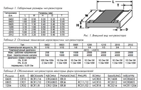
Figure 3. Resistor markings Figure 4 shows SMD surface mount resistors, also called "chip resistor". For amateur purposes, resistors of size 1206 are most suitable. They are quite large and have decent power, as much as 0.25 W. The same figure indicates that the maximum voltage for chip resistors is 200V. Resistors for conventional installation have the same maximum. Therefore, when a voltage is expected, for example 500V, it is better to install two resistors connected in series.
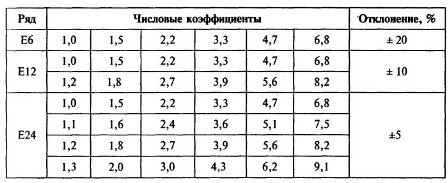
Figure 4. Surface Mount SMD Resistors Chip resistors of the smallest sizes are produced without markings, since there is simply nowhere to put them. Starting from size 0805, a three-digit marking is placed on the “back” of the resistor. The first two represent the denomination, and the third is a multiplier, in the form of an exponent of the number 10. Therefore, if, for example, 100 is written, then it will be 10 * 1 Ohm = 10 Ohm, since any number to the zero power is equal to one, the first two digits must be multiplied exactly by one . If the resistor says 103, then it turns out 10 * 1000 = 10 KOhm, and the inscription 474 says that we have a resistor 47 * 10,000 Ohm = 470 KOhm. Chip resistors with a tolerance of 1% are marked with a combination of letters and numbers, and the value can only be determined using a table that can be found on the Internet. Depending on the resistance tolerance, resistor values are divided into three rows, E6, E12, E24. The values of the denominations correspond to the figures in the table shown in Figure 5.
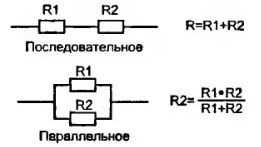
Figure 5. The table shows that the smaller the resistance tolerance, the more ratings in the corresponding row. If the E6 series has a 20% tolerance, then it has only 6 denominations, while the E24 series has 24 positions. But these are all resistors for general use. There are resistors with a tolerance of one percent or less, so any value can be found among them. In addition to power and nominal resistance, resistors have several more parameters, but we won’t talk about them for now. Connection of resistors Despite the fact that there are quite a lot of resistor values, sometimes you have to connect them to get the required value. There are several reasons for this: precise selection when setting up the circuit or simply the lack of the required nominal value. Basically, two resistor connection schemes are used: series and parallel. Connection diagrams are shown in Figure 6. Formulas for calculating the total resistance are also given there.
Figure 6. Resistor connection diagrams and formulas for calculating total resistance When serial connection the total resistance is simply the sum of the two resistances. It is as shown in the picture. In fact, there may be more resistors. Such inclusion occurs in . Naturally, the total resistance will be greater than the largest one. If these are 1KOhm and 10Ohm, then the total resistance will be 1.01KOhm. With a parallel connection, everything is just the opposite: the total resistance of two (or more resistors) will be less than the smaller one. If both resistors have the same value, then their total resistance will be equal to half of this value. You can connect a dozen resistors this way, then the total resistance will be just a tenth of the nominal value. For example, ten 100 ohm resistors are connected in parallel, then the total resistance is 100 / 10 = 10 ohms. It should be noted that in a parallel connection, according to Kirchhoff's law, the current will be divided into ten resistors. Therefore, the power required for each of them is ten times lower than for one resistor. Continue reading in the next article. Often, during an external inspection, damage to the varnish or enamel coating can be detected. A resistor with a charred surface or with rings on it is also faulty. A slight darkening of the varnish coating is acceptable for such resistors; the resistance value should be checked. The permissible deviation from the nominal value should not exceed ±20%. An increasing deviation of the resistance value from the nominal value is observed during long-term operation of high-resistance resistors (more than 1 MOhm). In some cases, a break in the conductive element does not cause any changes appearance resistor. Therefore, resistors are checked to ensure that their values correspond to the nominal values using an ohmmeter. Before measuring the resistance of resistors in the circuit, turn off the receiver and discharge the electrolytic capacitors. When measuring, it is necessary to ensure reliable contact between the terminals of the resistor being tested and the terminals of the device. To avoid shunting the device, do not touch the metal parts of the ohmmeter probes with your hands. The value of the measured resistance must correspond to the value indicated on the resistor body, taking into account the tolerance corresponding to the class of this resistor and the intrinsic error of the measuring device. For example, when measuring the resistance of a Class I accuracy resistor using the Ts-4324 device, the total error during measurement can reach ±15% (resistor tolerance ±5% plus instrument error ±10). If the resistor is checked without. If you remove it from the circuit, it is necessary to take into account the influence of shunt circuits. The most common fault with resistors is burnout of the conductive layer, which can be caused by the passage of an unacceptably large current through the resistor as a result of various short circuits in the installation or breakdown of the capacitor. Wirewound resistors are much less likely to fail. Their main faults (wire breakage or burnout) are usually found using an ohmmeter. Variable resistors (potentiometers) most often have poor contact between the moving brush and the conductive elements of the resistor. If such a potentiometer is used in a radio receiver to adjust the volume, then when its axis is rotated, crackling sounds are heard in the head of the dynamic loudspeaker. There are also breaks, wear or damage to the conductive layer. The serviceability of potentiometers is determined with an ohmmeter. To do this, connect one of the ohmmeter probes to the middle lobe of the potentiometer, and the second probe to one of the outer petals. With each such connection, the regulator axis is rotated very slowly. If the potentiometer is working properly, then the ohmmeter needle moves along the scale smoothly, without shaking or jerking. Trembling and jerking of the needle indicates poor contact of the brush with the conductive element. If the ohmmeter needle does not deflect at all, this means that the resistor is faulty. It is recommended to repeat this test by switching the second ohmmeter probe to the second outermost lobe of the resistor to make sure that this pin is also working properly. A faulty potentiometer must be replaced with a new one or repaired if possible. To do this, open the potentiometer housing and thoroughly wash the conductive element with alcohol and apply a thin layer of machine oil. Then it is reassembled and the reliability of the contact is checked again. Resistors found to be unsuitable are usually replaced with serviceable ones, the values of which are selected so that they correspond schematic diagram receiver If there is no resistor with the appropriate resistance, it can be replaced by two (or several) parallel or series connected. When connecting two resistors in parallel, the total resistance of the circuit can be calculated using the formula
where P is the power dissipated by the resistor, W; U is the voltage across the resistor. IN; R - resistor resistance value; Ohm. It is advisable to take a resistor with a slightly higher dissipation power (30,..40%) than that obtained in the calculation. If you do not have a resistor of the required power, you can select several smaller resistors. power and connect them together in parallel or in series so that their total resistance is equal to the one being replaced, and the total power is not lower than the required one. When determining interchangeability various types For the latter, constant and variable resistors also take into account the characteristics of the change in resistance depending on the angle of rotation of its axis. The choice of the potentiometer change characteristic is determined by its circuit purpose. For example, in order to obtain uniform control of the volume of a radio receiver, you should choose potentiometers of group B (with an exponential dependence of the change in resistance), and in the tone control circuits - group A. When replacing failed resistors of the BC type, we can recommend resistors of the MLT type with the appropriate dissipation power, having smaller dimensions and better moisture resistance. The rated power of the resistor and its accuracy class are not significant in the control grid circuits of lamps and collectors of low-power transistors.
A resistor serves to limit the current in an electrical circuit, create voltage drops in its individual sections, etc. There are a lot of applications, it’s impossible to count them all. Another name for a resistor is resistance. In fact, this is just a play on words, since translated from English resistance– is resistance (to electric current). When it comes to electronics, you can sometimes come across phrases like: “Replace the resistance”, “Two resistances have burned out”. Depending on the context, resistance may refer specifically to an electronic part. In the diagrams, a resistor is indicated by a rectangle with two terminals. On foreign diagrams it is depicted a little differently. The “body” of the resistor is indicated by a broken line - a kind of stylization of the first examples of resistors, the design of which was a coil wound with a high-resistance wire on an insulating frame.
Near symbol the element type is indicated ( R) and its serial number in the circuit (R 1 ). Its nominal resistance is also indicated here. If only a figure or number is indicated, then this resistance is in Ohms. Sometimes, next to the number they write Ω - so, Greek capital letter"Omega" stands for ohms. Well, if so, - 10 To, then this resistor has a resistance of 10 kilo Ohm (10 kOhm – 10,000 Ohm). You can talk about multipliers and prefixes “kilo” and “mega”. Do not forget about variable and tuning resistors, which are becoming increasingly rare, but are still found in modern electronics. About them device And parameters I have already told you on the pages of the site. Basic parameters of resistors.Nominal resistance. This is the factory resistance value of a particular device; this value is measured in Ohms (derivatives kiloohm– 1000 Ohm, megaohm– 1000000 Ohm). The resistance range extends from fractions of an Ohm (0.01 - 0.1 Ohm) to hundreds and thousands of kiloOhms (100 kOhm - 1 MOhm). Each electronic circuit requires its own sets of resistance values. That is why the spread of nominal resistance values is so large. Power dissipation. I have already written in more detail about resistor power. When passing electric current It heats up through the resistor. If a current exceeding a specified value is passed through it, the conductive coating will heat up so much that the resistor burns out. Therefore, there is a division of resistors according to power dissipation. On the graphical designation of a resistor inside a rectangle, power is indicated by an inclined, vertical or horizontal line. The figure shows the correspondence between the graphic designation and the power of the resistor indicated on the diagram.
For example, if a current of 0.1A (100 mA) flows through a resistor, and its nominal resistance is 100 Ohms, then a resistor with a power of at least 1 W is required. If you use a 0.5 W resistor instead, it will soon fail. Powerful resistors are used in high-current circuits, for example, in power supplies or welding inverters. If a resistor with a power of more than 2 W (5 W or more) is needed, then a Roman numeral is written inside the rectangle on the symbol. For example, V – 5 W, X – 10 W, XII – 12 W. Tolerance When manufacturing resistors, it is not possible to achieve absolute accuracy of the nominal resistance. If the resistor says 10 ohms, then its actual resistance will be around 10 ohms, but not exactly 10. It can be 9.88 or 10.5 ohms. In order to somehow indicate the error limits in the nominal resistance of resistors, they are divided into groups and assigned a tolerance. The tolerance is specified as a percentage. If you bought a 100 Ohm resistor with a tolerance of ±10%, then its actual resistance can be from 90 Ohms to 110 Ohms. You can find out the exact resistance of this resistor only using an ohmmeter or multimeter by taking the appropriate measurement. But one thing is certain. The resistance of this resistor will not be less than 90 or more than 110 ohms. Strict accuracy of resistance values in conventional equipment is not always important. For example, in consumer electronics it is allowed to replace resistors with a tolerance of ±20% of the value required in the circuit. This comes in handy in cases where it is necessary to replace a faulty resistor (for example, with a 10 Ohm one). If there is no suitable element with the required rating, then you can install a resistor with a nominal resistance from 8 Ohms (10-2 Ohms) to 12 Ohms (10+2 Ohms). It is calculated as follows (10 Ohm/100%) * 20% = 2 Ohm. The tolerance is -2 ohms in the direction of decrease, +2 ohms in the direction of increase. There is equipment where such a trick will not work - this is precision equipment. This includes medical equipment, measuring instruments, electronic components of high-precision systems, for example, military ones. In critical electronics, high-precision resistors are used, their tolerance is tenths and hundredths of a percent (0.1-0.01%). Sometimes such resistors can be found in consumer electronics. It is worth noting that currently on sale you can find resistors with a tolerance of no more than 10% (usually 1%, 5% and less often 10%). High-precision resistors have a tolerance of 0.25...0.05%. Temperature coefficient of resistance (TCR). Under the influence of external temperature or self-heating due to flowing current, the resistance of the resistor changes. Sometimes within limits that are undesirable for the operation of the circuit. To evaluate the change in resistance due to temperature, that is, the thermal stability of the resistor, a parameter such as TCR (Temperature Coefficient of Resistance) is used. Abbreviated as T.C.R. As a rule, the TCR value is not indicated in the resistor markings. For us, it is necessary to know that the lower the TCR, the better the resistor, since it has better thermal stability. I talked in more detail about such a parameter as TKS. The first three parameters are basic, you need to know them! Let's list them again: Nominal resistance (marked as 100 Ohm, 10kOhm, 1MOhm...) Power dissipation (measured in Watts: 1 W, 0.5 W, 5 W...) Tolerance (expressed as a percentage: 5%, 10%, 0.1%, 20%). It is also worth noting the design of the resistors. Nowadays they can be found as microminiature resistors for surface mounting ( SMD resistors), which do not have leads, and are powerful, in ceramic cases. There are also non-flammable, explosive and so on. The list could go on for a very long time, but their basic parameters are the same: rated resistance, power dissipation And admission. Currently, the nominal resistance of resistors and their tolerance are marked with colored stripes on the body of the element itself. As a rule, such marking is used for low-power resistors that have small dimensions and a power of less than 2...3 watts. Each manufacturer establishes its own labeling system, which creates some confusion. But basically there is one established marking system. For newcomers to electronics, I would also like to tell you that in addition to resistors, miniature capacitors in cylindrical cases are also marked with color stripes. This sometimes causes confusion because such capacitors are falsely mistaken for resistors. Color coding table.
Resistance is calculated using color stripes as follows. For example, the first three stripes are red, the last fourth is golden. Then the resistor resistance is 2.2 kOhm = 2200 Ohm. The first two numbers according to the red color are 22, the third red stripe is the multiplier. Therefore, according to the table, the multiplier for the red stripe is 100. You need to multiply the number 22 by the multiplier. Then, 22 * 100 = 2200 Ohms. The golden stripe represents a 5% tolerance. This means that the actual resistance can range from 2090 Ohms (2.09 kOhms) to 2310 Ohms (2.31 kOhms). The dissipation power depends on the size and design of the housing. In practice, resistors with a tolerance of 5 and 10% are widely used. Therefore, gold and silver stripes are responsible for admission. It is clear that in this case, the first stripe is on the opposite side of the element. This is where you need to start reading the denomination. But what if the resistor has a small tolerance, for example 1 or 2%? Which side should you read the denomination on if there are stripes of red and brown on both sides? This case was provided for and the first strip is placed closer to one of the edges of the resistor. This can be seen in the table figure. The stripes indicating tolerance are located further from the edge of the element. Of course, there are times when it is not possible to count color coding resistor (forgot the table, the marking itself was erased/damaged, incorrect stripes, etc.). In this case, you can find out the exact resistance of the resistor only if measure its resistance with a multimeter or an ohmmeter. In this case, you will 100% know its real value. Also, when assembling electronic devices, it is recommended to check resistors with a multimeter in order to eliminate possible defects. |


| Read: |
|---|
Popular:
Tortilla - what kind of Mexican dish is it and how to properly prepare it at home with photos
|
New
- Drawings on the theme no to fascism
- Posters from the Great Patriotic War
- Homemade chocolate without butter: recipes
- Raspberry tea recipe Raspberry tea recipe
- Canned Tuna Dip
- Lenten dishes: recipes for your favorite casseroles with potatoes and mushrooms (photo) Recipe for Lenten potato casserole with mushrooms
- Rainbow cake: recipe with photos
- Beef baked in foil in the oven
- A dish of eggplant with mushrooms and cheese in the oven: what could be simpler?
- Cooking in the oven: baked apples with honey How to make apples in the oven with honey


