Sections of the site
Editor's Choice:
- The role of temperament and character in the professional self-determination of a person
- The role of rhetoric in modern society
- Force method - calculation of statically indeterminate frames Calculate a plane statically indeterminate bar system
- Rhetoric is practiced speech, memory and breathing.
- Objective side of corpus delicti
- Invasive research methods
- MEA spoke about the future of world energy Energy future of the country
- The world of modern materials - laser principles
- Comparative analysis of the classical method of field seismic exploration and the Slip-Sweep method Two-dimensional seismic exploration method ogt
- Timeline of communication history
Advertising
| The simplest electrical circuits. How to read electronic circuits? Light switch off |
|
H in the pages This section publishes articles about what any beginner in radio electronics should know first of all. For many radio amateurs, electronics, once just a hobby, eventually grew into a professional environment, helped in finding a job, in choosing a profession. Taking the first steps in the study of radioelements, circuits, it seems that all this is terribly complicated. But gradually, with the accumulation of knowledge, the mysterious world of electronics becomes more understandable. E if You have always been interested in what is hidden under the cover of an electronic device, then you have come to the right place. Perhaps, a long and exciting journey in the world of radio electronics will start for you from this site! To go to the article of interest, click the link or the thumbnail image located next to brief description material. Measurements and instrumentation Any radio amateur needs a device that can check radio components. In most cases, electronics hobbyists use a digital multimeter for this purpose. But they can check not all elements, for example, MOSFET transistors. We bring to your attention an overview of the universal ESR L / C / R tester, which can also be used to test most semiconductor radioelements. An ammeter is one of the most important instruments in the laboratory of a novice radio amateur. Using it, you can measure the current consumed by the circuit, configure the operating mode of a specific unit in an electronic device, and much more. The article shows how in practice you can use an ammeter, which is mandatory in any modern multimeter. A voltmeter is a device for measuring voltage. How to use this device? How is it indicated on the diagram? You will learn more about this in this article. From this article you will learn how to determine the main characteristics of a dial voltmeter by the symbols on its scale. Learn to read the readings from the dial voltmeter scale. A practical example awaits you and you will also learn about interesting feature dial voltmeter, which you can use in your homemade products. How to check a transistor? This question is asked by all novice radio amateurs. Here's how to test a bipolar transistor with a digital multimeter. The method for checking the transistor is shown in specific examples with lots of photos and explanations. How to check a diode with a multimeter? Here is a detailed discussion of how you can determine the health of a diode with a digital multimeter. A detailed description of the test method and some "tricks" of using the diode test function of a digital multimeter. From time to time I am asked the question: "How to check a diode bridge?" And, it seems, I have already talked about the method of testing all kinds of diodes in sufficient detail, but I did not consider the method of testing a diode bridge in a monolithic assembly. Let's fill in this gap. If you still do not know what a decibel is, then we recommend that you slowly, carefully read the article about this entertaining unit of measurement of levels. After all, if you are engaged in radio electronics, then life will sooner or later make you understand what a decibel is. Often, in practice, it is required to convert microfarads to picofarads, millihenries to microhenries, milliamps to amperes, etc. How not to get confused when recalculating electrical values? This will help the table of factors and prefixes for the formation of decimal multiples and sub-multiples. In the process of repair and in the design of electronic devices, it becomes necessary to check capacitors. Often, seemingly serviceable capacitors have defects such as electrical breakdown, breakage or loss of capacity. Capacitors can be checked using widely used multimeters. Equivalent Series Resistance (or ESR) is a very important parameter for a capacitor. This is especially true for electrolytic capacitors operating in high-frequency pulse circuits. Why is ERS dangerous and why is it necessary to take into account its value when repairing and assembling electronic equipment? You will find the answers to these questions in this article. The power dissipation of a resistor is an important parameter of a resistor that directly affects the reliability of this element in an electronic circuit. This article explains how to evaluate and calculate the power of a resistor for use in an electronic circuit. Workshop of a beginner radio amateur How to read concepts? All novice electronics lovers face this question. Here you will learn how to learn to distinguish between the designations of radio components on schematic diagrams and take the first step in understanding the design of electronic circuits.
The most popular device in the laboratory of a novice radio amateur is an adjustable power supply. Here you will learn how, with a minimum of effort and time, to assemble an adjustable power supply 1.2 ... 32V based on a ready-made DC-DC converter module. Since you have decided to become a self-taught electrician, then surely after a short period of time you will want to make some useful electrical appliance for your home, car or summer cottage with your own hands. At the same time, homemade products can be useful not only in everyday life, but also made for sale, for example,. In fact, the process of assembling simple devices at home is not difficult. You just need to be able to read the diagrams and use the tool for radio amateurs. As for the first point, before you start making electronic homemade products with your own hands, you need to learn how to read electrical circuits. In this case, ours will be a good helper. From tools for novice electricians, a soldering iron, a set of screwdrivers, pliers and a multimeter will come in handy. For the assembly of some popular electrical appliances, you may even need welding machine but this is a rare case. By the way, in this section of the site we even talked about the same welding machine. Special attention should be paid to the materials at hand, from which every newbie electrician can make elementary electronic homemade products with his own hands. Most often, old domestic parts are used in the manufacture of simple and useful electrical appliances: transformers, amplifiers, wires, etc. In most cases, it is enough for novice radio amateurs and electricians to look for all the necessary tools in the garage or shed in the country. When everything is ready - the tools are assembled, the spare parts are found and the minimum knowledge is obtained, you can proceed to the assembly of amateur electronic homemade products at home. This is where our small guide will help you. Each provided instruction includes not only a detailed description of each of the stages of creating electrical appliances, but is also accompanied by photo examples, diagrams, as well as video lessons in which the entire manufacturing process is clearly shown. If you do not understand at some point, then you can clarify it under the entry in the comments. Our experts will try to advise you in a timely manner! Novice radio amateur: beginner radio amateur school, circuits and designs for beginners, literature, radio amateur programs Good day, dear radio amateurs! The site is running “ School for beginner radio amateurs“. The full course of study includes classes starting from the basics of radio electronics and ending with practical design radio amateur devices of average complexity of execution. Each lesson is based on providing students with the necessary theoretical information and practical videos, as well as homework. During the course of study, each student will receive the necessary knowledge and skills in the full cycle of designing radio electronic devices at home. In order to become a student of the school, you need a desire and a subscription to the site's news either through FeedBurner, or through the standard subscription window. A subscription is required to receive up-to-date lessons, class videos, and homework. Video materials and homework for the lessons will be available only to those who subscribe to the training course at the School for the Beginner Radio Amateur. For those who decided to study amateur radio with us, it is necessary, in addition to subscription, to carefully study the preparatory articles:
You can leave all questions, wishes and remarks in the comments in the section “Beginners”. First lesson. Second lesson. Third lesson. Fourth lesson.
Let's summarize some of the results of the School's work: If you went through all the steps sequentially, then your result should be as follows: 1. We learned: In the future, the "School" is planning to make a simple VHF radio receiver and a radio observer receiver. On this, most likely, the work of the "School" will be completed. In the future, basic articles for beginners will be published in the "Workshop" section. In addition, a new section on the study and programming of AVR microcontrollers has been started. Works by beginner radio amateurs: Intigrinov Alexander Vladimirovich:
Ruslan Volkov: There are several diagrams of simple devices and assemblies that can be made by novice radio amateurs. Single-stage AF amplifierit simplest design, which allows you to demonstrate the amplifying ability of the transistor True, the voltage gain is small - it does not exceed 6, so the scope of such a device is limited. Nevertheless, it can be connected, say, to a detector radio (it must be loaded with a 10 kΩ resistor) and use the BF1 headset to listen to the transmissions of the local radio station. The amplified signal is fed to the input jacks X1, X2, and the supply voltage (as in all other designs of this author, it is 6 V - four galvanic cells with a voltage of 1.5 V, connected in series) is fed to the jacks X3, X4. Divider R1R2 sets the bias voltage at the base of the transistor, and resistor R3 provides current feedback, which contributes to temperature stabilization of the amplifier. Rice. 1. Scheme of a single-stage AF amplifier on a transistor. How does stabilization take place? Let us assume that the transistor collector current has increased under the influence of temperature. Accordingly, the voltage drop across the resistor R3 will increase. As a result, the emitter current will decrease, and hence the collector current - it will reach its initial value. The load of the amplifier stage is a headset with a resistance of 60 .. 100 Ohm. It is not difficult to check the operation of the amplifier, you need to touch the input socket X1, for example, with tweezers a weak buzz should be heard in the phone, as a result of the induction of alternating current. The collector current of the transistor is about 3 mA. Two-stage ultrasonic frequency converter on transistors of different structuresIt is designed with direct coupling between stages and deep negative DC feedback, which makes it independent of the ambient temperature. The basis of temperature stabilization is the resistor R4, which works similarly to the resistor R3 in the previous design. The amplifier is more "sensitive" in comparison with a single-stage amplifier - the voltage gain reaches 20. AC voltage with an amplitude of no more than 30 mV can be applied to the input jacks, otherwise there will be distortions heard in the headphone. They check the amplifier by touching the input socket X1 with tweezers (or just with your finger) - the phone will hear loud noise... The amplifier draws a current of about 8 mA.
Rice. 2. Scheme of a two-stage AF amplifier based on transistors of different structures. This design can be used to amplify weak signals from a microphone, for example. And of course it will significantly enhance the signal 34 taken from the load of the detector receiver. Two-stage ultrasonic frequency converter on transistors of the same structureHere, a direct connection between the cascades is also used, but the stabilization of the operating mode is somewhat different from the previous designs. Suppose that the collector current of the transistor VT1 has decreased.The voltage drop across this transistor will increase, which will lead to an increase in the voltage across the resistor R3 connected to the emitter circuit of the transistor VT2. Due to the connection of the transistors through the resistor R2, the base current of the input transistor will increase, which will lead to an increase in its collector current. As a result, the initial change in the collector current of this transistor will be compensated.
Rice. 3. Scheme of a two-stage AF amplifier on transistors of the same structure. The sensitivity of the amplifier is very high - the gain reaches 100. The gain depends to a large extent on the capacitance of the capacitor C2 - if you turn it off, the gain will decrease. The input voltage should be no more than 2 mV. The amplifier works well with a detector receiver, electret microphone, and other weak signal sources. The current consumed by the amplifier is about 2 mA. It is made on transistors of different structures and has a voltage gain of about 10. The highest input voltage can be 0.1 V. The first two-stage amplifier is assembled on the VT1 transistor, the second - on VT2 and VTZ of different structures. The first stage amplifies the voltage signal 34, with both half-waves being the same. The second one amplifies the current signal, but the cascade on the VT2 transistor “works” with positive half-waves, and on the VTZ transistor - with negative ones.
Rice. 4. Push-pull power amplifier AF on transistors. The DC mode is chosen such that the voltage at the junction point of the emitters of the second stage transistors is approximately half the voltage of the power supply. This is achieved by switching on the feedback resistor R2. The collector current of the input transistor, flowing through the diode VD1, leads to a voltage drop across it. which is the bias voltage at the bases of the output transistors (relative to their emitters) - it allows you to reduce the distortion of the amplified signal. The load (several headphones connected in parallel or a dynamic head) is connected to the amplifier through an oxide capacitor C2. If the amplifier will operate on a dynamic head (with a resistance of 8-10 ohms), the capacitance of this capacitor should be at least twice as large. Pay attention to the connection of the load of the first stage - resistor R4. , and with the lower output of the load. This is the so-called voltage boost circuit, in which a small voltage of the AF positive feedback enters the base circuit of the output transistors, which equalizes the operating conditions of the transistors. Two-level voltage indicatorSuch a device can be used. for example, to indicate the "exhaustion" of the battery or indicate the level of the reproduced signal in a household tape recorder. The indicator layout will demonstrate how it works.
Rice. 5. Scheme of a two-level voltage indicator. In the lower position of the engine of the variable resistor R1, both transistors are closed, the LEDs HL1, HL2 are off. When you move the resistor slider up, the voltage across it increases. When it reaches the opening voltage of the VT1 transistor, the HL1 LED will flash If you continue to move the engine. there will come a moment when, after the diode VD1, the transistor VT2 opens. The HL2 LED will also flash. In other words, a low voltage at the indicator input causes only the HL1 LED to light up and more than both LEDs. Smoothly decreasing the input voltage with a variable resistor, we note that the HL2 LED goes out first, and then HL1. The brightness of the LEDs depends on the limiting resistors R3 and R6 as their resistances increase, the brightness decreases. To connect the indicator to a real device, you need to disconnect the upper terminal of the variable resistor from the positive wire of the power source and apply a controlled voltage to the extreme terminals of this resistor. By moving its slider, the indicator response threshold is selected. When monitoring only the voltage of the power source, it is permissible to install a green LED AL307G in place of HL2. It emits light signals on the principle of less than normal - normal - more than normal. For this, the indicator uses two red and one green LEDs.
Rice. 6. Three-level voltage indicator. At a certain voltage on the engine of the variable resistor R1 (voltage is normal), both transistors are closed and only the green LED HL3 is working. Moving the resistor slider up the circuit leads to an increase in voltage (more than normal), the VT1 transistor opens on it. The HL3 LED goes out and HL1 comes on. If the slider is moved down and thus the voltage across it is reduced (‘less than normal”), the VT1 transistor will close and VT2 will open. The following picture will be observed: first, the HL1 LED will go out, then HL3 will light up and soon go out, and finally HL2 will flash. Due to the low sensitivity of the indicator, a smooth transition from the extinguishing of one LED to the ignition of another is obtained has not yet completely extinguished, for example, HL1, but HL3 is already on. Schmitt triggerAs you know, this device is usually used to convert a slowly varying voltage into a square wave signal. When the slider of the variable resistor R1 is in the lower position according to the circuit, the transistor VT1 is closed. The voltage at its collector is high, as a result, the VT2 transistor turns out to be open, which means that the HL1 LED is on. A voltage drop forms on the resistor R3.
Rice. 7. Simple Schmitt trigger on two transistors. By slowly moving the variable resistor slider up the circuit, it will be possible to reach the moment when the VT1 transistor suddenly opens and VT2 closes.This will happen when the voltage at the base of VT1 exceeds the voltage drop across the resistor R3. The LED will turn off. If you then move the slider down, the trigger will return to its original position - the LED will flash. This will happen when the voltage on the slider is less than the LED off voltage. Waiting multivibratorSuch a device has one stable state and passes into another only when an input signal is applied. In this case, the multivibrator generates a pulse of its own duration, regardless of the duration of the input signal. We will verify this by conducting an experiment with the layout of the proposed device.
Rice. 8. Schematic diagram of the waiting multivibrator. In the initial state, the VT2 transistor is open, the HL1 LED is on. It is now enough to short-circuit the slots X1 and X2 for a current pulse through the capacitor C1 to open the VT1 transistor. The voltage on its collector will decrease and the capacitor C2 will be connected to the base of the VT2 transistor in such a polarity that it will close. The LED will turn off. The capacitor will start to discharge, the discharge current will flow through the resistor R5, keeping the VT2 transistor closed. As soon as the capacitor is discharged, the VT2 transistor will open again and the multivibrator will go back to standby mode. The duration of the pulse generated by the multivibrator (the duration of being in an unstable state) does not depend on the duration of the trigger, but is determined by the resistance of the resistor R5 and the capacitance of the capacitor C2. If you connect a capacitor of the same capacity in parallel to C2, the LED will remain off for twice as long. I. Bokomchev. P-06-2000. Below are simple light and sound circuits, mainly assembled on the basis of multivibrators, for novice radio amateurs. In all schemes, the simplest element base is used, no complicated adjustment is required, and replacement of elements with similar ones within a wide range is allowed. Electronic duck The toy duck can be equipped with a simple "quacking" simulator circuit on two transistors. The circuit is a classic multivibrator on two transistors, in one arm of which an acoustic capsule is connected, and the load of the other is two LEDs that can be inserted into the eyes of the toy. Both of these loads work alternately - either a sound is heard, then LEDs flash - the eyes of a duck. As a power switch SA1, you can use a reed switch (can be taken from the sensors SMK-1, SMK-3, etc., used in systems burglar alarm as door opening sensors). When the magnet is brought to the reed switch, its contacts are closed and the circuit begins to work. This can happen when the toy is tilted to a hidden magnet or a kind of "magic wand" with a magnet is presented. The transistors in the circuit can be any p-n-p type, low or medium power, for example MP39 - MP42 (old type), KT 209, KT502, KT814, with a gain of more than 50. You can also use transistors n-p-n structures, for example KT315, KT 342, KT503, but then you need to change the polarity of the power supply, turn on the LEDs and the polar capacitor C1. As an acoustic radiator BF1, you can use a capsule of the TM-2 type or a small-sized speaker. The establishment of the circuit is reduced to the selection of the resistor R1 to obtain a characteristic quack sound. The sound of a bouncing metal ball The circuit quite accurately simulates such a sound, as the capacitor C1 discharges, the volume of the "blows" decreases, and the pauses between them decrease. At the end, a characteristic metallic bounce will be heard, after which the sound will stop.
Transistors can be replaced with similar ones as in the previous circuit. Engine Sound Simulator They can, for example, sound a radio-controlled or other model of a mobile device.
Options for replacing transistors and dynamics - as in the previous circuits. Transformer T1 - output from any small-sized radio receiver (a speaker is also connected to the receivers through it). There are many schemes for simulating the sounds of birdsong, animal voices, a locomotive whistle, etc. The circuit proposed below is assembled on just one digital microcircuit K176LA7 (K561 LA7, 564LA7) and allows you to simulate many different sounds depending on the value of the resistance connected to the input contacts X1.
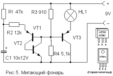
It should be noted that the microcircuit works "without power" here, that is, no voltage is applied to its positive terminal (leg 14). Although in fact the microcircuit is still powered, this happens only when the resistance-sensor is connected to the X1 contacts. Each of the eight inputs of the microcircuit is connected to the internal power bus through diodes that protect against static electricity or miswiring. Through these internal diodes, the microcircuit is powered due to the presence of positive feedback on the power supply through the input resistor-sensor. The circuit represents two multivibrators. The first (on elements DD1.1, DD1.2) immediately begins to generate rectangular pulses with a frequency of 1 ... 3 Hz, and the second (DD1.3, DD1.4) is switched on when the logical level is received at pin 8 from the first multivibrator. 1". It generates tone pulses with a frequency of 200 ... 2000 Hz. From the output of the second multivibrator, the pulses are fed to the power amplifier (transistor VT1) and a modulated sound is heard from the dynamic head. If now a variable resistor with a resistance of up to 100 kOhm is connected to the input jacks X1, then there is a feedback on the power supply and this transforms the monotonous intermittent sound. By moving the slider of this resistor and changing the resistance, you can achieve a sound reminiscent of the trill of a nightingale, chirping of a sparrow, quacking of a duck, croaking of a frog, etc. Details The power switch can be omitted in this circuit, since in the rest mode the device consumes less than 1 μA current, which is much less than even the self-discharge current of any battery! Adjustment Flashlight The frequency of flashing of the lamp can be adjusted by selecting the elements R1, R2, C1. The lamp can be from a flashlight or an automobile 12V. Depending on this, you need to choose the supply voltage of the circuit (from 6 to 12 V) and the power of the switching transistor VT3.
Transistors VT1, VT2 - any low-power corresponding structure (KT312, KT315, KT342, KT 503 (n-p-n) and KT361, KT645, KT502 (p-n-p), and VT3 - medium or high power (KT814, KT816, KT818). A simple device for listening to the soundtrack of TV programs on headphones. Does not require any power supply and allows you to move freely within the room.
Coil L1 is a "loop" of 5 ... 6 turns of wire PEV (PEL) -0.3 ... 0.5 mm, laid along the perimeter of the room. It is connected in parallel to the TV speaker through the SA1 switch as shown in the figure. For normal operation of the device, the output power of the audio channel of the TV should be within 2… 4 W, and the loop resistance should be 4… 8 Ohm. The wire can be laid under the skirting board or in a cable duct, and it should be placed, if possible, no closer than 50 cm from the 220 V mains wires to reduce alternating voltage pickups.
The L2 coil is wound on a frame made of thick cardboard or plastic in the form of a ring with a diameter of 15 ... 18 cm, which serves as a headband. It contains 500 ... 800 turns of wire PEV (PEL) 0.1 ... 0.15 mm fixed with glue or electrical tape. A miniature volume control R and an earphone (high-impedance, for example TON-2) are connected in series to the terminals of the coil. Light switch off This differs from many schemes of similar automata in its extreme simplicity and reliability, and in detailed description does not need. It allows you to turn on the lighting or any electrical appliance for a specified short time, and then automatically turns it off.
To turn on the load, it is enough to briefly press the SA1 switch without latching. In this case, the capacitor has time to charge and opens the transistor, which controls the switching on of the relay. The turn-on time is determined by the capacitance of the capacitor C and with the rating indicated in the diagram (4700 mF) is about 4 minutes. An increase in the on time is achieved by connecting additional capacitors in parallel with C. The transistor can be any n-p-n type of medium power or even low-power, such as KT315. It depends on the operating current of the relay used, which can also be any other for an operating voltage of 6-12 V and is capable of switching the load of the power you need. You can use and pnp transistors type, but it will be necessary to change the polarity of the supply voltage and turn on the capacitor C. Resistor R also affects the response time within small limits and can be 15 ... 47 kOhm, depending on the type of transistor. List of radioelements
|
|||||||||||||||||||||||||||||||||||||||||||||||||||||||||||||||||||||||||||||||||||||||||||||||||||||||||||||||||||||||||||||||||||||||||||||||||||||||||||||||||||||||||||||||||||||||||||||||||||||||||||||||||||||||||||||||||||||||||||||||||||||||||||||
 WITH where to start studying radio electronics? How to build your first electronic circuit? Can you quickly learn to solder? It is for those who ask such questions that the section has been created. "Start"
.
WITH where to start studying radio electronics? How to build your first electronic circuit? Can you quickly learn to solder? It is for those who ask such questions that the section has been created. "Start"
. DIY power supply. The power supply is an indispensable attribute in a radio amateur's workshop. Here you will learn how to independently assemble a regulated power supply with a switching stabilizer.


| Read: |
|---|
Popular:

New
- Traveling through forgotten kingdoms - jan jansen jan jansen
- How to choose your style of clothing for men: good advice from experts
- Where to buy new home appliances with minor defects?
- Men's T-shirts with slogans Off-shoulder models
- Business style in clothes for men
- Where does men's style begin?
- Intimissimi underwear
- Ekaterina smolina fashion house
- The most unusual heels. The most unusual shoes. Metallic, transparent and colored sphere
- World Trade Center


