Sections of the site
Editor's Choice:
- Frejka pillow sizes by age
- Sports knee brace
- Water programs in X-Fit: training according to the unique SMART SWIM method
- Anti-varicose compression hosiery
- XVIII World Class Games: results
- Oleg Vasiliev: every step in my life is against the movement
- Son of Elena Sanzharovskaya: cause of death, what happened
- Orenburg bibliographic encyclopedia
- SketchUp - a program for modeling simple 3D objects
- Pole Dance (Paul Dance, Pole Dance)
Advertising
| Diy schemes of amateur radio devices. DIY amateur radio circuits and homemade products |
|
Those who do electronics at home are usually very curious. Amateur radio schemes and homemade products will help you find a new direction in creativity. Perhaps someone will find for themselves original solution this or that problem. Some homemade products use ready-made devices, connecting them in various ways. For others, you need to completely create the circuit yourself and make the necessary adjustments. One of the simplest homemade products. More suitable for those who are just starting to tinker. If you have an old but working cellular push-button telephone with a button to turn on the player, you can make, for example, a doorbell to your room from it. The advantages of such a call:  First, you need to make sure that the selected phone is capable of producing a sufficiently loud melody, after which it must be completely disassembled. Basically, parts are fastened with screws or brackets, which are carefully folded back. When disassembling, you will need to remember what is behind what, so that later you can collect everything.
Homemade products for carsModern cars are equipped with everything you need. However, there are times when homemade devices are simply needed. For example, something broke, given to a friend and the like. Then the ability to create electronics with your own hands at home will be very useful. The first thing you can intervene in without fear of damaging your car is the battery. If at the right time the charging for the battery was not at hand, you can quickly assemble it yourself. This will require:  A transformer from a tube TV is ideal. Therefore, those who are addicted to homemade electronics never throw away electrical appliances in the hope that they will be needed someday. Unfortunately, there are two types of transformers used: with one and with two coils. Anyone will go to charge a 6 volt battery, and only two for 12 volts. The wrapping paper of such a transformer shows the winding leads, the voltage for each winding, and the operating current. To power the filaments of electronic lamps, a voltage of 6.3 V with a high current is used. The transformer can be altered by removing the extra secondary windings, or left as it is. In this case, the primary and secondary windings are connected in series. Each primary is designed for a voltage of 127 V, therefore, combining them, they get 220 V. The secondary ones are connected in series to get 12.6 V. The diodes must withstand a current of at least 10 A. Each diode requires a radiator with an area of \u200b\u200bat least 25 square centimeters. They are connected to a diode bridge. Any insulating plate is suitable for fastening. A 0.5 A fuse is included in the primary circuit, and a 10 A fuse in the secondary circuit. The device does not tolerate a short circuit, therefore, when connecting the battery, the polarity must not be confused.
Simple heatersIn the cold season, it may be necessary to warm up the engine. If the car is parked where there is an electric current, this problem can be solved by using a heat gun. To make it you will need:
The diameter of the asbestos pipe is chosen according to the size of the fan to be used. The performance of the heater will depend on its power. Pipe length is everyone's preference. You can collect in it a heating element and a fan, only a heater is possible. When choosing the last option, you will have to think about how to start up the air flow to the heating element. This can be done, for example, by placing all the components in a sealed enclosure. Nichrome wire is also picked up by the fan. The more powerful the latter, the larger diameter nichrome can be used. The wire is twisted into a spiral and placed inside the pipe. For fastening, bolts are used that are inserted into pre-drilled holes in the pipe. The length of the spiral and their number are chosen empirically. It is desirable that the spiral does not get red-hot when the fan is running.
Some problems can be solved by using another homemade product. Instead of an asbestos pipe, you can use a coffee can. To prevent the spiral from closing on the jar, it is attached to a textolite frame, which is fixed with glue. A cooler is used as a fan. To power it, you will need to assemble another electronic device - a small rectifier.
Home-made products bring the person who deals with them, not only satisfaction, but also benefit. With their help, you can save energy, for example, by turning off electrical appliances that you forgot to turn off. A time relay can be used for this purpose. The easiest way to create a timing element is to use the time to charge or discharge the capacitor through the resistor. Such a chain is included in the base of the transistor. The diagram will require the following details:
First you need to determine what current will be switched through the relay. If the load is very powerful, you will need a magnetic starter to connect it. The starter coil can be connected via a relay. It is important that the relay contacts can work freely without sticking. A transistor is selected according to the selected relay, it is determined with what current and voltage it can work. You can focus on KT973A.
The capacitor itself is connected to the positive rail of the power supply through a variable resistor with high resistance. By choosing the capacitance of the capacitor and the resistance of the resistor, you can change the delay time interval. The relay coil is shunted by a diode, which turns on in the opposite direction. This circuit uses KD 105 B. It closes the circuit when the relay is de-energized, protecting the transistor from breakdown.
The capacitor begins to charge through a resistor connected to the positive terminal of the power supply. As the capacitor charges, the base voltage begins to rise. At a certain voltage value, the transistor closes, de-energizing the relay. The relay disconnects the load. To make the circuit work again, you need to discharge the capacitor, for this switch the switch.
You can make the simplest electronic circuits for use in everyday life with your own hands, even without deep knowledge of electronics. In fact, at the household level, radio is very simple. Knowledge of the elementary laws of electrical engineering (Ohm, Kirchhoff), the general principles of operation of semiconductor devices, the skills of reading circuits, the ability to work with an electric soldering iron is enough to assemble the simplest circuit. Radio amateur workshopNo matter how complex the scheme would have to be performed, you must have a minimum set of materials and tools in your home workshop:
You should not purchase expensive professional tools and devices to begin with. An expensive soldering station or digital oscilloscope is of little help to a novice radio amateur. At the beginning of the creative path, there are quite enough simple devices on which you need to hone your experience and skill.
Where to startDo-it-yourself radio circuits for the house should not exceed the complexity of the level that you own, otherwise it will only mean wasted time and materials. With a lack of experience, it is better to limit yourself to the simplest schemes, and as skills accumulate, improve them, replacing them with more complex ones. Typically, most of the electronics literature for beginner radio amateurs gives a classic example of making the simplest receivers. This is especially true of the classical old literature, in which there are not so many fundamental mistakes in comparison with the modern one. Note! These schemes were designed for the enormous power of transmitting radio stations in the past. Today, transmitting centers use less power to transmit and try to move into the shorter wavelength range. You should not waste time trying to make a working radio receiver using the simplest circuit. Radio circuits for beginners should include a maximum of a couple of active elements - transistors. This will make it easier to understand the operation of the circuit and increase the level of knowledge. What can be doneWhat can be done to make it easy and can be used in practice at home? There can be many options:
Important! Do not design AC household appliances until you have sufficient experience. It is dangerous for life and for others. Quite simple circuits have amplifiers for computer speakers, made on specialized integrated circuits. Devices assembled on their basis contain a minimum number of elements and practically do not require adjustment. You can often find circuits that need elementary alterations, improvements that simplify manufacturing and customization. But this should be done by an experienced master so that the final version is more accessible to a beginner. On what to carry out the structureMost of the literature recommends designing simple circuits on circuit boards. Nowadays, this is quite simple. A wide variety of circuit boards are available with various bore and track configurations. The principle of installation is that the parts are installed on the board in free places, and then the necessary terminals are connected with jumpers, as indicated in the circuit diagram.
With proper care, such a board can serve as the basis for many circuits. The power of the soldering iron for soldering should not exceed 25 W, then the risk of overheating the radio elements and printed conductors will be minimized. The solder should be low-melting, such as POS-60, and it is best to use pure pine rosin or its solution in ethyl alcohol as a flux. Highly qualified radio amateurs can design a printed circuit board themselves and execute it on foil material, on which they can then solder radioelements. The structure developed in this way will have optimal dimensions. Completion of the finished structureLooking at the creations of beginners and experienced craftsmen, one can come to the conclusion that assembling and adjusting a device is not always the most difficult part of the design process. Sometimes a properly working device remains a set of parts with soldered wires, not covered by any case. Nowadays, you can no longer be puzzled by the manufacture of the case, because on sale you can find all kinds of sets of cases of any configurations and dimensions.
Before starting the manufacture of the design you like, you should fully think over all the stages of the work: from the availability of tools and all radio elements to the version of the case. It will be completely uninteresting if, in the process of work, it turns out that one of the resistors is missing, and there are no replacement options. It is better to carry out the work under the guidance of an experienced radio amateur, and, in extreme cases, periodically monitor the manufacturing process at each stage. Video
Below are simple light and sound circuits, mainly assembled on the basis of multivibrators, for novice radio amateurs. In all the schemes, the simplest element base is used, no complicated adjustment is required and it is allowed to replace elements with similar ones within a wide range. Electronic duck The toy duck can be equipped with a simple "quacking" simulator circuit on two transistors. The circuit is a classic multivibrator on two transistors, in one arm of which an acoustic capsule is connected, and the load of the other is two LEDs that can be inserted into the toy's eyes. Both of these loads work alternately - either a sound is heard, or LEDs flash - the eyes of a duck. A reed switch can be used as a power switch SA1 (can be taken from the sensors SMK-1, SMK-3, etc., used in systems burglar alarm as door opening sensors). When the magnet is brought to the reed switch, its contacts are closed and the circuit begins to work. This can happen when the toy is tilted to a hidden magnet or a kind of "magic wand" with a magnet is presented. The transistors in the circuit can be any p-n-p type, low or medium power, for example MP39 - MP42 (old type), KT 209, KT502, KT814, with a gain of more than 50. You can also use transistors of the npn structure, for example KT315, KT 342, KT503, but then you need to change the polarity of the power supply, turning on LEDs and polar capacitor C1. As an acoustic radiator BF1, you can use a capsule of the TM-2 type or a small-sized speaker. The establishment of the circuit is reduced to the selection of the resistor R1 to obtain a characteristic quack sound. The sound of a bouncing metal ball The circuit quite accurately simulates such a sound, as the capacitor C1 discharges, the volume of the "blows" decreases, and the pauses between them decrease. At the end, a characteristic metallic bounce will be heard, after which the sound will stop.
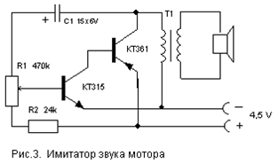
Transistors can be replaced with similar ones as in the previous circuit. Engine Sound Simulator They can, for example, sound a radio-controlled or other model of a mobile device.
The options for replacing transistors and dynamics are the same as in the previous circuits. Transformer T1 - output from any small-sized radio receiver (a speaker is also connected to the receivers through it). There are many schemes for imitating the sounds of birdsong, animal voices, a locomotive horn, etc. The circuit proposed below is assembled on just one digital microcircuit K176LA7 (K561 LA7, 564LA7) and allows you to simulate many different sounds depending on the value of the resistance connected to the input contacts X1.
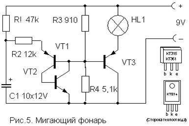
It should be noted that the microcircuit works here "without power", that is, no voltage is applied to its positive terminal (leg 14). Although in fact the microcircuit is still powered, this happens only when the resistance-sensor is connected to the X1 contacts. Each of the eight inputs of the microcircuit is connected to the internal power bus through diodes that protect against static electricity or miswiring. It is through these internal diodes that the microcircuit is powered due to the presence of positive feedback on the power supply through the input resistor-sensor. The circuit represents two multivibrators. The first (on the elements DD1.1, DD1.2) immediately starts to generate rectangular pulses with a frequency of 1 ... 3 Hz, and the second (DD1.3, DD1.4) is switched on when the logical level is sent to pin 8 from the first multivibrator. 1". It generates tonal pulses with a frequency of 200 ... 2000 Hz. From the output of the second multivibrator, the pulses are fed to the power amplifier (transistor VT1) and a modulated sound is heard from the dynamic head. If now a variable resistor with a resistance of up to 100 kOhm is connected to the input jacks X1, then there is a power feedback and this transforms the monotonous intermittent sound. By moving the slider of this resistor and changing the resistance, you can achieve a sound reminiscent of the trill of a nightingale, chirping of a sparrow, quacking of a duck, croaking of a frog, etc. Details The power switch can be omitted in this circuit, since the device consumes less than 1 μA current in rest mode, which is much less than even the self-discharge current of any battery! Adjustment Flashlight The frequency of flashing of the lamp can be adjusted by selecting the elements R1, R2, C1. The lamp can be from a flashlight or a car 12V. Depending on this, you need to choose the supply voltage of the circuit (from 6 to 12 V) and the power of the switching transistor VT3.
Transistors VT1, VT2 - any low-power corresponding structure (KT312, KT315, KT342, KT 503 (n-p-n) and KT361, KT645, KT502 (p-n-p), and VT3 - medium or high power (KT814, KT816, KT818). A simple device for listening to the soundtrack of TV programs on headphones. Does not require any power supply and allows you to move freely within the room.
Coil L1 is a "loop" of 5 ... 6 turns of wire PEV (PEL) -0.3 ... 0.5 mm, laid along the perimeter of the room. It is connected in parallel to the TV speaker through the SA1 switch as shown in the figure. For normal operation of the device, the output power of the TV audio channel should be within 2… 4 W, and the loop resistance should be 4… 8 Ohm. The wire can be laid under the skirting board or in a cable duct, and it must be placed, if possible, no closer than 50 cm from the 220 V mains wires to reduce AC voltage pickups.
The L2 coil is wound on a frame made of thick cardboard or plastic in the form of a ring 15 ... 18 cm in diameter, which serves as a headband. It contains 500 ... 800 turns of wire PEV (PEL) 0.1 ... 0.15 mm fixed with glue or electrical tape. A miniature volume control R and an earphone (high impedance, for example TON-2) are connected in series to the terminals of the coil. Light switch off This differs from many schemes of similar automata in its extreme simplicity and reliability and in detailed description does not need. It allows you to turn on the lighting or any electrical appliance for a specified short time, and then automatically turns it off.
To turn on the load, it is enough to briefly press the SA1 switch without latching. In this case, the capacitor has time to charge and opens the transistor, which controls the switching on of the relay. The turn-on time is determined by the capacitance of the capacitor C and with the rating indicated in the diagram (4700 mF) is about 4 minutes. An increase in the on time is achieved by connecting additional capacitors in parallel with C. The transistor can be any n-p-n type of medium power or even low-power, such as KT315. It depends on the operating current of the relay used, which can also be any other for an operating voltage of 6-12 V and capable of switching the load of the power you need. You can also use p-n-p type transistors, but you will need to change the polarity of the supply voltage and the switching on of the capacitor C. Resistor R also affects the response time within small limits and can be 15 ... 47 kOhm, depending on the type of transistor. List of radioelements
Homemade measuring instrument circuitsThe circuit of the device, developed on the basis of a classic multivibrator, but instead of load resistors, transistors with opposite main conductivity are included in the collector circuits of the multivibrator. It's good if your lab has an oscilloscope. Well, if it is not there and it is not possible to buy it for one reason or another, do not worry. In most cases, it can be successfully replaced by a logic probe, which allows you to check the logic levels of signals at the inputs and outputs of digital integrated circuits, determine the presence of pulses in the controlled circuit and reflect the information received in visual (light-color or digital) or audio (tones of various frequencies ) forms. When establishing and repairing structures on digital integrated circuits, it is far from always so necessary to know the characteristics of the pulses or the exact values \u200b\u200bof voltage levels. Therefore, logic probes facilitate the setup process, even if you have an oscilloscope. A huge selection of different pulse generator circuits is presented. Some of them form a single pulse at the output, the duration of which does not depend on the duration of the triggering (input) pulse. Such generators are used for a wide variety of purposes: simulating input signals of digital devices, when checking the performance of digital integrated circuits, the need to supply a certain number of pulses to a device with visual control of processes, etc. Others generate sawtooth and rectangular pulses of various frequencies, duty cycles and amplitudes The repair of various nodes and devices of low-frequency electronic equipment and equipment can be significantly simplified if you use a functional generator as an assistant, which makes it possible to study the amplitude-frequency characteristics of any low-frequency device, transient processes and nonlinear characteristics of any analog devices, and also has the ability to generate rectangular pulses form and simplify the process of setting up digital circuits. When setting up digital devices, you definitely need another device - a pulse generator. An industrial generator is a rather expensive device and is rarely on sale, but its analog, albeit not so accurate and stable, can be assembled from available radioelements at home However, the creation of a sound generator that generates a sinusoidal signal is not easy and rather painstaking, especially in terms of adjustment. The fact is that any generator contains at least two elements: an amplifier and a frequency-dependent circuit that determines the oscillation frequency. It is usually connected between the output and the input of the amplifier, creating positive feedback (PIC). In the case of an RF generator, everything is simple - an amplifier on one transistor and an oscillating circuit that determines the frequency is enough. For the audio frequency range, winding the coil is difficult, and its quality factor is low. Therefore, in the range of audio frequencies, RC elements are used - resistors and capacitors. They filter the fundamental harmonic of the oscillations rather poorly, and therefore the sinusoidal signal turns out to be distorted, for example, limited by the peaks. To eliminate distortion, amplitude stabilization circuits are used, which maintain a low level of the generated signal when the distortion is still invisible. It is the creation of a good stabilizing circuit that does not distort the sinusoidal signal that causes the main difficulties. Often, having assembled the structure, the radio amateur sees that the device does not work. After all, a person does not have sense organs that allow one to see an electric current, an electromagnetic field or the processes taking place in electronic circuits. Radio measuring devices help to do this - the eyes and ears of the radio amateur. Therefore, we need some means of testing and checking phones and loudspeakers, audio amplifiers, various sound recording and sound reproducing devices. Such a tool is an amateur radio circuit for audio frequency signal generators, or, more simply, a sound generator. Traditionally, it generates a continuous sinusoidal signal, the frequency and amplitude of which can be changed. This allows you to check all the ULF cascades, find faults, determine the gain, remove the amplitude-frequency characteristics (AFC) and much more. Considered a simple amateur radio homemade prefix that turns your multimeter into a universal device for checking zener diodes and dinistors. PCB drawings available So. Life turned out so that I have a house in the village with gas heating... It is impossible to live there all the time. The house is used as a summer residence. For a couple of winters, I stupidly left the boiler on with a minimum coolant temperature. Connecting a motion sensor 4 pins do it yourself diagramDiy motion sensor connection diagram
It happens that you need to install in the country, or in the house lighting that will be triggered when moving or a person or someone else. The motion sensor, which I ordered from Aliexpress, is good for this function. The link to which will be below. By connecting shine through the motion sensor, when a person passes through his field of vision, the light turns on, burns for 1 minute. and turns off again. In this article I will tell you how to connect such a sensor if it does not have 3 contacts, but 4 like this one. DIY power supply from an energy-saving light bulb
DIY fan speed controller
This regulator allows you to smoothly adjust variable resistor fan speed. The floor fan speed controller circuit turned out to be the simplest. To fit into the body from an old Nokia phone charger. Terminals from an ordinary electrical outlet also fit in there. The installation is quite tight, but this was due to the size of the case .. DIY lighting for plantsDIY lighting for plants There is a problem with a lack of lighting plants, flowers or seedlings, and there is a need for artificial light for them, and this is the kind of light we can provide on LEDs do it yourself. Diy brightness controlDiy brightness control
It all started with the fact that after I installed halogen lamps for lighting at home. When turned on, which often burned out. Sometimes even 1 light bulb a day. Therefore, I decided to make a smooth switching on of the lighting based on the dimmer with my own hands, and I am attaching the dimmer circuit. DIY refrigerator thermostatDIY refrigerator thermostat
It all started with the fact that after returning from work and opening the refrigerator, he found it warm. Turning the thermostat knob did not help - the cold did not appear. Therefore, I decided not to buy a new unit, which is also rare, but to make an electronic thermostat myself on the ATtiny85. With the original thermostat, the difference is that the temperature sensor is on the shelf, and not hidden in the wall. In addition, 2 LEDs have appeared - they signal that the unit is on or the temperature is above the upper threshold. DIY soil moisture sensorDIY soil moisture sensor
This device can be used for automatic irrigation in greenhouses, flower greenhouses, flower beds and indoor plants... Below is a diagram by which you can make the simplest sensor (detector) of moisture (or dryness) of the soil with your own hands. When the soil dries up, a voltage is supplied with a current strength of up to 90mA, which is quite enough, turn on the relay. Also suitable for automatic activation drip irrigation to avoid excess moisture. Fluorescent lamp power circuitFluorescent lamp power circuit.
Often, when energy-saving lamps fail, it burns out power circuit, and not the lamp itself. As known, LDS with burned-out filaments, it is necessary to supply with rectified mains current using a starless starting device. In this case, the filaments of the lamp are shunted with a jumper and to which a high voltage is applied to turn on the lamp. There is an instant cold ignition of the lamp, a sharp increase in the voltage across it, when starting without preheating the electrodes. In this article we will look at do-it-yourself lds lamp start. USB keyboard for tabletUSB keyboard for tablet
Somehow, suddenly, he took something and decided to buy a new keyboard for his PC. The desire for novelty cannot be overcome. Changed the background color from white to black and the color of the letters from red-black to white. A week later, the desire for novelty naturally went like water into sand (an old friend is better than two new ones) and the new thing was sent to the closet for storage - until better times. And so they came for her, did not even imagine that it would happen so quickly. And therefore the name would be even better suited not which is, but how to connect a usb keyboard to a tablet. |
|||||||||||||||||||||||||||||||||||||||||||||||||||||||||||||||||||||||||||||||||||||||||||||||||||||||||||||||||||||||||||||||||||||||||||||||||||||||||||||||||||||||||||||||||||||||||||||||||||||||||||||||||||||||||||||||||||||||||||||||||||||||||||||

 The entire heater is connected to the network via a cord with a plug, but it itself must have its own switch. It can be either just a toggle switch or an automatic machine. The second option is more preferable, it allows you to protect the general network. For this, the tripping current of the machine must be less than the operating current of the room machine. The switch is also needed to quickly turn off the heater in case of malfunctions, for example, if the fan does not work. This heater has its drawbacks:
 The scheme works as follows. In the initial state, the base of the transistor is disconnected from the capacitor and the transistor is closed. When the switch is turned on, the base is connected to the discharged capacitor, the transistor opens and supplies voltage to the relay. The relay works, closes its contacts and supplies voltage to the load.


 When to get 12 Volts for


| Read: |
|---|

New
- “What is the scene in a dream?
- If a child catches a parent having sex
- Dream interpretation to be in an unfamiliar city
- Collect roses in a dream. Why do roses dream. Dream interpretation of Martin Zadeki
- Whole oven baked tuna: recipes with cheese and vegetables
- Straight talk: how to conduct it
- Carl Jung's dream theory
- Monkey fold: causes, symptoms, diagnosis, treatment, correction and advice from doctors
- How to cook white beans properly
- Seeing yourself rich in a dream


