|
Insulation tests with increased voltage are carried out to detect concentrated defects in the insulation of electrical equipment that were not detected in preliminary tests due to an insufficient level of electric field strength. The overvoltage test is the main test, after which a final judgment is made on the possibility of normal operation of the equipment under operating conditions.
An increased voltage test is mandatory for electrical equipment with a voltage of 35 kV and below, and if test devices are available, for equipment with a voltage above 35 kV, except as otherwise specified by the standards.
Insulators and equipment with a rated voltage exceeding the rated voltage of the installation in which they are operated may be tested with increased voltage in accordance with the standards established for the insulation class of this installation.
The established level of test voltages corresponds to the breakdown voltages of insulation in the presence of concentrated defects in them.
The level of test voltages of electrical equipment when it is put into operation is lower than the factory test voltages and is 0.9.Usp.zav. This is explained by the fact that in the process of testing it is inappropriate to develop minor defects that do not affect normal operation to dangerous ones, which, reducing the dielectric strength, may appear during operation.
A power frequency voltage of 50 Hz is usually used as a test voltage. The duration of the application of the test voltage is limited in order to avoid the appearance of defects in the insulation and its premature aging from 1 min to 5 min.
When testing the insulation of large electrical machines, switch rods, arresters, power cables with voltages over 1 kV, a rectified voltage is used as a test voltage.
The main disadvantage of the rectified voltage test is the uneven distribution of voltage over the thickness of the insulation (due to heterogeneity) depending on the conductivity of its individual parts.
However, rectified voltage testing also has advantages:
1. The rectified voltage is less dangerous for insulation (the breakdown rectified voltage is higher than the alternating voltage, on average 1.5 times).
2. In machines, the distribution of voltage along the insulation of the winding is more even with a rectified voltage, due to which the lower and frontal parts of it are equally tested.
3. The required power of high voltage rectifiers is much less than that of alternating voltages, so that mobile units are always less bulky and therefore more portable, and it is possible to test objects with large capacitance (capacitor cables, etc.).
In addition, during such tests, it is possible to measure leakage currents, which are an additional criterion for assessing the state of the insulation. Insulation tests with rectified voltage are longer than tests with alternating voltage, and range from 10 to 20 minutes.
Where the insulation test is carried out with both a.c. and rectified voltage, the rectified voltage test shall precede the a.c. voltage test.
Testing the insulation of electrical equipment with high voltage is carried out after a preliminary inspection and checking the condition of the insulation using a megohmmeter and other indirect additional methods (measurements tgδ, ΔC / C, C2 / C50) with positive results of this test. The test voltage and test duration for each type of equipment is determined by the established standards.
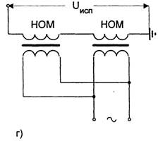
Tests with increased voltage in the general case are carried out according to the scheme shown in Fig. 1.1.
The rate of voltage increase to one third of the test value can be arbitrary, in the future the test voltage should be increased smoothly, at a speed that allows visual reading on measuring instruments. After the set test duration, the voltage gradually decreases to a value not exceeding one third of the test voltage, and is turned off. Sudden removal of voltage is allowed only in cases of ensuring the safety of people or the safety of electrical equipment.
To prevent unacceptable overvoltages during testing (due to higher harmonic components in the test voltage curve), the test installation should be connected, if possible, to the line voltage of the network (the most dangerous third harmonic is absent in the line voltage).
The test voltage is usually measured on the low voltage side. Exceptions are critical insulation tests for generators, large electric motors, etc.
Rice. 1.1. Scheme for testing the insulation of electrical equipment with increased AC voltage.
1 - automatic switch; 2 - adjusting column; 3, 10 - voltmeter; 4 - ammeter for measuring current on the low voltage side; 5 - test transformer; 6 - milliammeter for measuring the leakage current of the tested insulation; 7 - button that shunts the miliammeter to protect it from overload; 8 - voltage transformer; 9 - resistor for limiting the current in the test transformer during breakdowns in the insulation under test (1-2 ohms per 1 V of the test voltage); 11 - the same for limiting switching overvoltages on the insulation under test during the breakdown of the arrester (1 ohm per 1 V of test voltage); 12- arrester; 13 - tested object. The capacitance of the object under test can have a significant impact on testing. So for objects with a large capacity, the test voltage may exceed the normalized voltage due to the capacitive voltage boost. Also, capacitance has a significant impact on the choice of power of the test setup, which is determined by
Where C is the capacitance of the tested insulation, pF; Utest - test voltage, kV; ω is the angular frequency of the test voltage (ω = 2πf).
The approximate capacity of some test objects is given in Table. 1.1.
The power of the test set is adjusted to the rated voltage of the test transformer

Table 1.1. Approximate capacity of electrical equipment
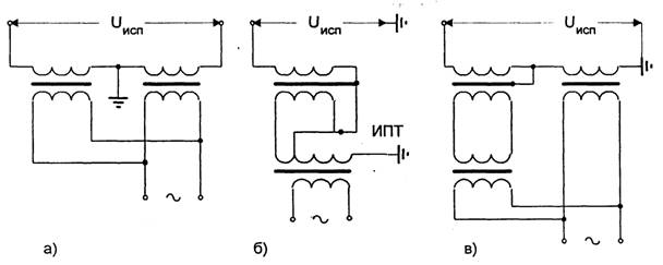
Rice. 1.2. Test voltage doubling circuits.
IPT - isolating intermediate transformer; NOM - single-phase voltage transformer; a) the insulation under test is isolated from the body.
In the event that the required power for testing exceeds the power of the available transformers, they resort to reducing it by compensating for the capacitive load current of the tested insulation. Compensation is carried out by inductance (arc reactor, specially made choke) connected in parallel with the tested insulation.
If the rated voltage of the test set is less than the required rated test voltage, then two test transformers (or voltage instrument transformers) are connected in series. Possible switching schemes are shown in fig. 1.2. When using NOM voltage transformers, it is allowed to increase the voltage on the primary winding of the measuring transformer up to 150-170% of the rated voltage.
To protect against accidental dangerous voltage surges in test facilities, protective arresters are provided. The arrester consists of two brass balls up to 10 cm in diameter, mounted on bakelite racks. One ball is fixed motionless, and the second one can move along the guides of the base. Depending on the required breakdown voltage, the distance between the balls is set using a micrometric screw. The breakdown voltage of the air gap between the balls should not exceed 10-15% of the value of the normalized test voltage.
To protect the surface of the balls from combustion during breakdowns, non-inductive resistors (porcelain or glass, filled with water) 2-20 kOhm are connected in series with them.
When carrying out tests, it is necessary to exclude the possibility of overlapping by air of the insulation on the grounded parts of the tested object and parts under operating voltage (see Table 1.2).
Table 1.2. Minimum allowable air distances for testing
|
test
voltage, kV
|
Distance cm
|
|
to grounded
parts
|
to parts of the installation under voltage, kV
|
|
|
|
|
|
|
|
|
|
|
|
|
|
|
|
|
|
|
|
|
|
|
|
|
|
|
|
|
|
|
|
|
|
|
|
|
|
|
|
|
|
|
|
|
|
|
|
|
|
|
|
|
|
|
|
|
|
|
|
|
|
|
|
|
|
|
|
|
|
|
|
|
|
|
|
|
|
|
|
|
|
|
|
|
|
|
|
|
|
|
|
|
|
|
|
|
|
|
|
|
|
|
|
|
|
|
|
|
|
|
|
|
|
|
|
|
|
|
|
|
|
|
|
|
|
|
|
|
|
|
|
|
|
|
|
|
|
|
|
|
|
|
|
|
|
|
|
|
|
|
|
|
|
|
|
|
|
|
|
|
|
|
|
|
|
|
|
|
|
|
|
|
|
|
|
|
|
|
|
|
|
|
|
|
|
|
|
|
|
|
|
|
|
|
|
|
|
|
|
|
|
|
|
|
|
|
|
|
|
|
|
|
|
|
To test insulation with rectified voltage, as a rule, a half-wave rectification circuit is used (Fig. 1.3).
Rice. 1.3. Scheme of testing the insulation of electrical equipment with rectified voltage.
1 - automatic switch; 2 - adjusting column; 3 - voltmeter; 4-test transformer; 5 - rectifier; 6 - milliammeter for measuring the leakage current of the tested insulation; 7 - button that shunts the miliammeter to protect it from overload; 8 - limiting resistor; 9 - tested object.
The procedure for carrying out tests is similar to tests on alternating current, in addition, control over the leakage current must be additionally carried out.
The load of the test transformer is negligible, since it is determined by losses in the DC insulation resistance, so a voltage measuring transformer can be used for testing. The test voltage is usually measured on the low voltage side of the test transformer. Therefore, when measuring, it is necessary to take into account the transformation ratio of the transformer, and multiply the final result by J2 (because the rectified voltage is determined by the amplitude value, and the voltmeter records the effective value of the applied voltage).
After testing with rectified voltage, it is necessary to discharge the test object with particular care. To remove the charge from the test object, grounding rods are used, the electrical circuit of which includes a resistance of 5-50 kOhm. As the latter, for objects with a large capacity, rubber tubes filled with water are used. After the test object is discharged, it must be tightly grounded.
The AII-70 installation is designed to test the elegiac strength of the insulation of electrical installation elements, incl. power cables and liquid dielectrics (transformer oil) direct (rectified) or high voltage alternating current. Rectified high voltage - 70 kV, variable high - 50 kV. Supply voltage 127, 220 V. Maximum rectified current - 5 mA; the output one-minute power of the high-voltage transformer is 2 kVA. Operating time under load (with kenotron prefix) - 10 min.; the interval between inclusions is 3 minutes; weight - 175 kg. The anode network of the kenotron includes a microammeter unit with measurement limits of 200, 1000 and 5000 μA. The test voltage is measured with a voltmeter connected to the low side of the transformer and calibrated for effective values (up to 50 kV) and maximum values (up to 70 kV). Protection (sensitive and coarser) against short circuit is built into the kenotron apparatus. on the high voltage side. The set of the device includes a grounding rod designed to remove the capacitive charge from the test object and its deaf grounding.
AIM-80 installation provides test voltage up to 80 kV.
Currently, installations are used in which, instead of a kenotron, semiconductor high-voltage rectifiers of the VVK-0.05/140, VVK-05/200, etc. types are used. The VVK-0.05/140 installation has the following technical characteristics: maximum rectified voltage - 70 kV ; maximum rectified current 50 mA; maximum reverse voltage - 140 kV. Overall dimensions - diameter 130 mm, height 440 mm, weight 6 kg. The setup is a set of D-1008 diodes (10 kV, 50 mA) shunted with a POV capacitor (15 kV) and placed in an insulating tube.
The VChF-4-3 universal apparatus is designed to test the electrical strength of the turn insulation of the windings of AC and DC electrical machines with a power of 0.1 - 100 kW and more; windings of rotors of turbogenerators; pole coils of synchronous generators and DC machines; windings of power transformers 1, 11, W dimensions; windings of current transformers. Supply voltage 220 V, power consumption up to 800 VA; output (adjustable) voltage 3000 V.
Mobile electrical laboratories based on the GAZ-51 chassis (old models) ETL-10M are designed for measurements and tests during commissioning and during preventive maintenance of electrical installations with voltage up to 10 kV inclusive, as well as for drying transformer oil and electric welding.
ETL-35-02 based on the GAZ-66 chassis are designed to carry out a full range of measuring and testing work on the equipment of 35/10 kV substations with a power of up to 600 kVA and power plants, overhead and cable lines up to 35 kV, as well as to determine the location of damage in cable lines with voltage up to 10 kV.
The most modern of the above facilities is the LVI2G laboratory, the capabilities and technical characteristics of which are similar to the ETL-35-02 mobile laboratory.
Mobile laboratories include incinerators PKLS-10, CCGT.
Insulation resistance is an important characteristic of the state of insulation of electrical equipment. Therefore, resistance measurement is carried out during all inspections of the condition of the insulation.
Insulation resistance is measured with a megaohmmeter. Electronic megaohmmeters of the F4101, F4102 type for voltages of 100, 500 and 1000 V have found wide application. and 2500 V. The error of the F4101 device does not exceed ± 2.5%, and of the M4100 type devices - up to 1% of the length of the working part of the scale. The F4101 device is powered from an AC network of 127-220 V or from a 12 V DC source. The devices of the M4100 type are powered from built-in generators.
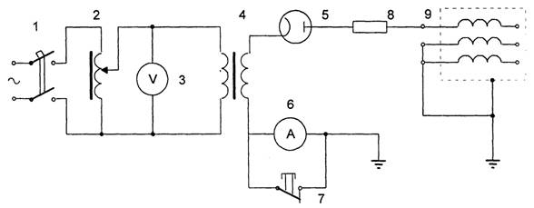
Insulation measurement is carried out according to the schemes of fig. 1.4.
If the measurement result can be distorted by surface leakage currents, an electrode is applied to the insulation of the measurement object, which is connected to the E terminal (screen) to exclude the possibility of leakage currents passing through the frame of the ratiometer used in instruments as a measuring body. When measuring the insulation resistance of a cable, the metal sheath of the cable can serve as such a screen.
Before starting the measurement, the device must be checked by short-circuiting clamps Z and L. The device should show resistance 0, and with a remote short circuit, the resistance is equal to infinity. Immediately before the measurement, the measurement object must be grounded for 2 - 3 minutes to remove residual charges.
When measuring the absolute value of the insulation resistance of electrical equipment, its current-carrying part is connected by wires with reinforced insulation (PVL type) to the terminal L of the megohmmeter. Conclusion 3 and the housing or structures against which the measurement is made are reliably grounded through a common ground loop. The insulation resistance is determined by the indication of the megohmmeter needle, which has been established after 60 s after the application of normal voltage.
Rice. 1.4. Schemes for measuring insulation resistance with a megohmmeter 1. a - relative to the ground; b - between current-carrying (rods); c - between current-carrying conductors with the exclusion of the influence of leakage currents.
The insulation resistance value is highly dependent on temperature.
The measurement should be carried out at an insulation temperature of at least +5°C, unless otherwise specified.
The insulation of electrical equipment in the general case can be represented by an equivalent equivalent circuit (Fig. 1.5, a). The current flowing in the insulation (dielectric) under the action of the applied voltage is represented on the vector diagram (Fig. 1.5.6) by the active 1A and capacitive 1C components. Power losses in the insulation (dielectric losses) significantly depend on the state of the insulation and are determined by: Р = U.IA = U.I.cosφ = U.IC.tgδ = C.U2.tgδ. Thus, the power loss P is proportional to tgδ (the tangent of the dielectric loss angle). Measurement tgδ is used to assess the state of insulation, regardless of the weight and size characteristics of the latter. The larger tgδ, the greater the dielectric losses, the worse the state of the insulation.
In practice, tgδ is measured as a percentage.
The value of tgδ is normalized for electrical equipment and depends on the temperature and the magnitude of the applied voltage. Measurement of tgδ should be carried out at a temperature not lower than +10°С. Correction factors are used to bring the measured values of tgδ to the required temperature (for example, the temperature during measurements at the plant).
Measurement of tgδ is carried out by bridges P5026, MD-16 and P595 at high (3 - 10 kV) and low voltage. For the tangent of the dielectric loss angle, the relation is valid: tgδ \u003d RX / XCX \u003d ω.RX.CX (see Fig. 1.5). When the bridge is in equilibrium, the equality takes place: ω.Rх.Cх = ω.R4.C4 (see Fig. 1.6). Thus, the measured tgδ is proportional to the capacitance C4 changing to balance the bridge. This is the basis for the principle of measuring tgδ by the bridges mentioned above. In table. 1.3 shows the measurement limits of bridges.
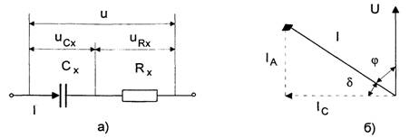
Rice. 1.5. Equivalent circuit of a dielectric.
a - dielectric equivalent circuit; b - vector diagram.
Table 1.3. Capacitance measurement limits of measuring bridges
On fig. 1.6 shows a normal (direct) circuit for switching on measuring bridges. This switching circuit is used for measurements on objects in which both electrodes are isolated from the ground. An inverted (reverse) bridge connection scheme is also used, in which the bridge clamps for grounding and voltage supply are reversed. The inverted pattern is less accurate than the normal pattern. However, measurements of tgδ insulation of transformers, as well as bushings installed on the equipment, can only be performed in an inverted scheme, since one of the electrodes is grounded in these cases.
The value of tgδ insulation is measured at a voltage equal to the rated voltage of the measurement object, but not higher than 10 kV. At a rated voltage of an object less than 6 kV, measurements are made at a voltage of 220 - 380 V. Measurements are made with satisfactory results of assessing the state of the insulation using a megohmmeter and other methods and satisfactory test results of an oil sample of oil-filled apparatus. Measurements during drying of the insulation are carried out at a voltage of 220 - 380 V. The results of tgδ measurements are compared with the permissible standards and the results of previous measurements, including factory ones.
As a test transformer, voltage transformers NOM-6 or NOM-10 are used. The transformer is connected according to the diagram in fig. 1.7. To ensure measurement accuracy, the bridge and auxiliary equipment necessary for the measurement are located in close proximity to the object under test (Fig. 1.8), since the bridge takes into account losses in the connecting wire.
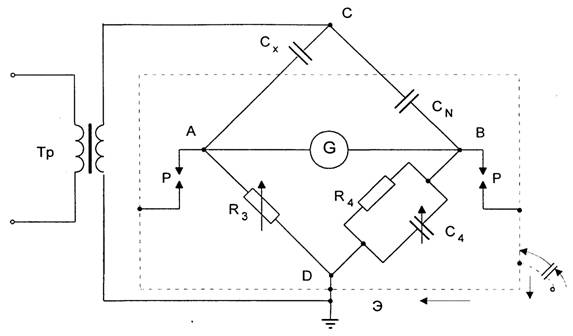
Rice. 1.6. Normal (direct) AC bridge circuit.
Tp - test transformer; СN - exemplary capacitor; CX - tested object;
G - galvanometer; R3 - variable resistor; R4 - constant resistor; C4 - container store.
The main methods for measuring DC resistance are: indirect method; method of direct estimation and bridge method.
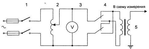
Rice. 1.7. Scheme of switching on the test transformer when measuring tgδ.
1 - knife switch; 2 - adjusting autotransformer; 3 - voltmeter; 4-switch the polarity of the outputs of the test transformer 5.
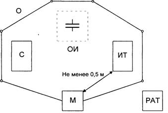
Rice. 1.8. Scheme of arrangement of devices during measurement.
OI - measurement object; C - exemplary capacitor; T - test transformer; M - bridge; PAT-regulating autotransformer; 0 - portable fence.
The choice of measurement method depends on the expected value of the measured resistance and the required accuracy.
The most versatile of the indirect methods is the ammeter-voltmeter method.
Ammeter-voltmeter method. It is based on measuring the current flowing through the measured resistance and the voltage drop across it. Two measurement schemes are used: the measurement of large resistances (Fig. 1.9, a) and the measurement of low resistances (Fig. 1.9, b). According to the results of measuring current and voltage, the desired resistance is determined.
For the scheme of Fig. 1.9, and the desired resistance and the relative methodological measurement error are determined
Where RX is the measured resistance; Ra is the resistance of the ammeter.
For the scheme of Fig. 1.9.6 the desired resistance and the relative methodological measurement error are determined

where Rv is the resistance of the voltmeter.
From the definition of relative methodological errors, it follows that the measurement according to the scheme of Fig. 1.9,a provides a smaller error when measuring high resistances, and the measurement according to the circuit in Fig. 1.9.6 - when measuring low resistances.
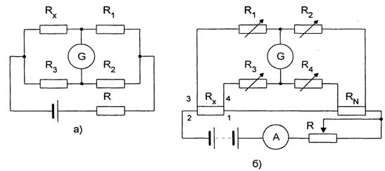
The measurement error by this method is calculated by the expression
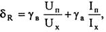
where γв, γа, are the accuracy classes of the voltmeter and ammeter; U „, I measurement limits of the voltmeter and ammeter.
The devices used in the measurement must have an accuracy class of not more than 0.2. The voltmeter is connected directly to the measured resistance. The current during measurement should be such that the readings are read on the second half of the scale. In accordance with this, the shunt is also selected, which is used to be able to measure the current with a class 0.2 device. To avoid heating the resistance and, accordingly, reducing the accuracy of measurements, the current in the measurement circuit should not exceed 20% of the nominal.
Rice. 1.9. Scheme for measuring large (a) and small (b) resistances using the ammeter-voltmeter method.
It is recommended to carry out 3 - 5 measurements at different current values. For the result, in this case, the average value of the measured resistances is taken.
When measuring resistance in circuits with high inductance, the voltmeter should be connected after the current in the circuit is established, and disconnected before the current circuit breaks. This must be done in order to exclude the possibility of damage to the voltmeter from the self-induction EMF of the measurement circuit.
Method of direct assessment. It involves measuring DC resistance with an ohmmeter. Measurements with an ohmmeter give significant inaccuracies. For this reason, this method is used for approximate preliminary measurements of resistances and for testing switching circuits. In practice, ohmmeters such as M57D, M4125, F410, etc. are used. The range of measured resistances of these devices lies in the range from 0.1 Ohm to 1000 kOhm.
To measure low resistances, for example, the resistance of soldering anchor windings of DC machines, microohmmeters of the M246 type are used. These are ratiometric type instruments with an optical indicator, equipped with special self-cleaning probes.
Also, for measuring low resistances, for example, the transient resistances of switch contacts, contactometers have been used. Mosenergo contactometers have measurement limits of 0 - 50,000 μΩ with an error of less than 1.5%. Contactometers KMS-68, KMS-63 allow measurements in the range of 500-2500 μΩ with an error of less than 5%.
To measure the resistance of the windings of power transformers, generators with a sufficiently high accuracy, DC potentiometers of the PP-63, KP-59 type are used. These devices use the principle of compensation measurement, i.e. the voltage drop across the measured resistance is balanced by a known voltage drop.
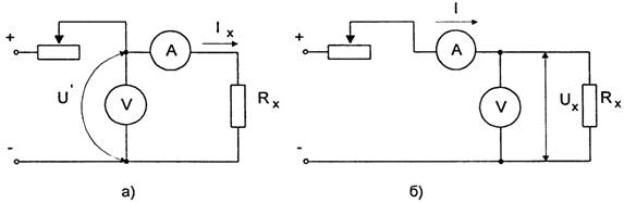
Bridge method. Two measurement schemes are used - a single bridge scheme and a double bridge scheme. The corresponding measurement schemes are shown in Figs. 1.10.
To measure resistance in the range from 1 Ohm to 1 MΩ, single DC bridges of the MMV, R333, MO-62, etc. types are used. The measurement error with these bridges reaches 15% (MMV bridge). In single bridges, the measurement result takes into account the resistance of the connecting wires between the bridge and the measured resistance. Therefore, resistances less than 1 ohm cannot be measured with such bridges due to a significant error. The exception is the P333 bridge, which can be used to measure high resistances using a two-terminal circuit and low resistances (up to 5 10 Ohms) using a four-terminal circuit. In the latter, the influence of the resistance of the connecting wires is almost eliminated, since two of them enter the galvanometer circuit, and the other two enter the resistance circuit of the bridge arms, which have relatively high resistances.
Rice. 1.10. Schemes of measuring bridges.
a - single bridge; b - double bridge.
The shoulders of single bridges are made from resistance stores, and in some cases (for example, the MMV bridge), the shoulders R2, R3 can be made of a calibrated wire (rheochord), along which the engine connected to the galvanometer moves. The equilibrium condition of the bridge is determined by the expression Rх = R3.(R1/R2). With R1, the ratio R1/R2 is set, usually a multiple of 10, and with R3, the bridge is balanced. In bridges with a rheochord, balancing is achieved by a smooth change in the ratio R3/R2 at fixed values of R1.
In double bridges, the resistance of the connecting wires is not taken into account during measurements, which makes it possible to measure resistances up to 10-6 Ohm. In practice, single-double bridges such as P329, P3009, MOD-61, etc. are used with a measurement range from 10-8 Ohm to 104 MΩ with a measurement error of 0.01 - 2%.
In these bridges, equilibrium is achieved by changing the resistances R1, R2, R3 and R4. In this case, the equalities R1 = R3 and R2 = R4 are achieved. The equilibrium condition of the bridge is determined by the expression Rх= RN.(R1/R2). Here the resistance RN is the exemplary resistance, an integral part of the bridge. Four wires are connected to the measured resistance Rx: wire 2 is the continuation of the bridge power circuit, its resistance does not affect the measurement accuracy; wires 3 and 4 are connected in series with resistances R1 and R2 greater than 10 ohms, so that their influence is limited; wire 1 is an integral part of the bridge and should be chosen as short and thick as possible.
When measuring resistance in circuits with a large inductance, in order to avoid errors and to prevent damage to the galvanometer, it is necessary to measure at a steady current, and turn off before breaking the current circuit.
Measurement of resistance to direct current, regardless of the measurement method, is carried out under a steady thermal regime, in which the ambient temperature differs from the temperature of the measured object by no more than ± 3 ° C. To convert the measured resistance to another temperature (for example, for comparison purposes, to 15°C), conversion formulas are used.
|