Sections of the site
Editor's Choice:
- How to unlock ariston washing machine
- Pros and cons of LED lighting
- Pulse relay: device and connection
- How to calculate the illumination of a room with LED lamps?
- Plastic box - do-it-yourself aesthetic view of electrical wiring
- Electricity consumption of a warm floor: electric and film
- Installing a pump in a well: how to properly install pumping equipment
- Electrician Toolkit Overview
- How to choose a water heater: the most complete list of evaluation criteria
- 1 acoustics on the example of Sven SPS-860 and Realtek ALC889 codec
Advertising
| How to use the current clamp |
|
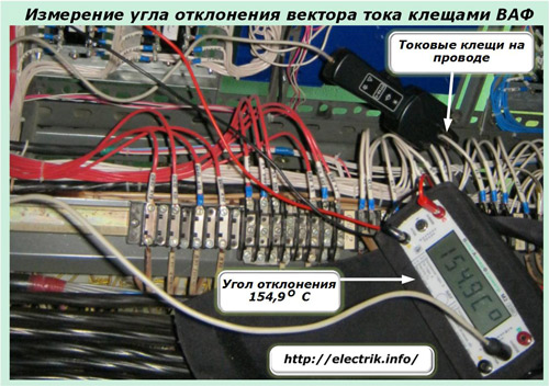
When evaluating the condition of existing electrical installations or performing repairs under voltage, electricians have to measure and compare the values of currents flowing through various chains. This allows you to analyze the operational scheme, in a timely manner to eliminate emerging faults. Quite often, all this must be done without breaking the electrical circuits so as not to disrupt the technological process of supplying consumers with electricity. There are two ways to measure load currents without interrupting the power supply: 1. ordinary ammeters, first creating bypass shunt chains through them and putting them into operation due to an artificial current break in a pre-prepared place. At the end of the measurements, it is required to restore the electrical circuit, perform all previous technological operations in reverse order; 2. using a tool specially designed for this purpose - current clamps. The first method of measurement is complicated, time-consuming, dangerous, requires highly qualified workers, good preliminary training. Therefore, they try to use it only in extreme cases, and in everyday practice, measurements are performed by current clamps. What are the types of current clamps Most often in practice they are encountered with direct (rectified) or alternating sinusoidal current. For both of these types, various designs of clamps have been created that can measure the magnitude and even the direction of power flow without breaking the power supply circuit of consumers in an existing electrical installation. The photo below shows the measurement of the deviation of the angle of the current vector from the direction of the base voltage in the measuring circuits of protective devices.
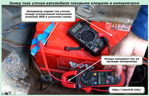
The method for measuring leakage currents through the broken insulation of the electrical equipment of a car using DC clamps and an ammeter is shown in the photograph.
The measuring circuit used is assembled in such a way that the clamps themselves show the current flowing through the wire connected to the ammeter clamp. Both devices demonstrate the same value, although they operate at different sensitivity ranges. This example clearly demonstrates the convenience and accuracy of measurement with various devices. DC current clamps are less common than AC designs, but their production has increased significantly in recent years. It should also be borne in mind that manufacturers of measuring equipment have now launched the production of combined-use clamps that can work in DC and AC circuits. Such a design, for example, is embodied in the Fluke 376 and the like.
The current clamps shown in the first three photographs have a digital display that immediately displays the primary values of the measured parameters of the electrical circuit. But, in the arsenal of measuring instruments of electricians, a large number of devices with arrow pointers and a scale consisting of several subranges still work. When using such structures, it is necessary to carefully read the reading, and sometimes introduce correction factors. According to the magnitude of the applied voltage, current clamps are divided into devices operating: up to 1000 volts; or above 1 kV. They differ in the protection class of the insulation used and require different compliance with safety rules. To properly use any such devices, you need to know the principle of their operation and design. How current measuring clamps are arranged The device of various models can differ significantly depending on the timing of their manufacture and the complexity of the internal circuit. But the principles of measurement and controls are almost identical everywhere. Therefore, we will take the Fluke 376 model as the basis for the study, which has great capabilities and, accordingly, has an increased number of functions and controls for them. Principles of operation incorporated in the design
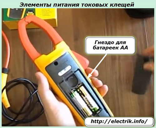
In the dielectric case of any device are placed: a current transformer with (a) a detachable magnetic drive and a system of its control levers, (b) a secondary winding; measuring system with information board; controls and switching modes of operation; contact sockets. To power the current clamps, the electrical energy of the measured circuit or a set of autonomous voltage sources, for example, two AA batteries, can be used.
The work is based on an ordinary current transformer with a detachable magnetic circuit and a secondary winding, the turns of which are crossed by a magnetic flux that induces a secondary current into them. Its value, and in some designs and direction, is determined by the measuring system, which displays the final result on the display, taking into account the transformation ratio in primary amperes. To perform the measurement, it is necessary to place a conductor with current inside the magnetic circuit. For this: by pressing the key, the moving elements of the magnetic circuit are bred; a current-carrying wire is inserted into the gap formed; release the key and monitor the full contact of the moving contacts.
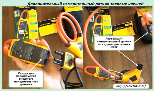
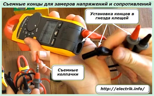
When working inside cramped cabinets with a lot of electrical equipment, it is sometimes difficult to pass the tip of the sliding magnetic circuit through a current-carrying conductor. To simplify this operation, the Fluke 376 has an optional test probe. It is included in the set of the device and, if necessary, can be easily prepared for measurement.
For safe work under voltage, the pliers are equipped with measuring ends with insulating tips and caps. When installed in the body of the device, they are recessed into its design. Together with well-insulated tips, this reduces possible errors in operation, eliminates unauthorized creation of accidental short circuits and electrical injury.
Clamp controls The positions of the circular mode switch are shown by text inserts in the third picture from the top. Their work is complemented by control buttons located on the case.
The ZERO button is used to switch within the clamp modes set by the central round switch, and the MIN / MAX button allows you to refine the measurement limit. The INRUSH button is designed to evaluate the inrush current. The convenience of using the device in a darkened workplace is significantly provided by the built-in backlight, which is put into operation by pressing the rightmost button at the bottom with the image of lighting. To fix the current readings on the display, a HOLD button is installed near the side surface of the pliers.
For some models of current clamps, some of these functions may be absent or implemented in other ways, but the general principles of measurement are preserved for all such devices. How to make current clamp measurements Preparatory operations Before each measurement, it is necessary to check the influence of extraneous voltage sources and the interference they create on the accuracy of the device.
Powerful asynchronous electric motors, power transformers and autotransformers, chokes, welding machines, during operation, can create strong electromagnetic fields that will induce an induced EMF in the magnetic circuit. To take them into account, the clamps are placed in the position of measuring alternating current, the sliding elements of the magnetic circuit are tightly closed and the zero reading of the currents on the display is controlled. Methods for measuring currents The design of the measuring device allows you to determine the magnitude of the current by simple actions: setting the mode switches to the appropriate position and inserting the conductor into the space of the sliding magnetic circuit. The numerical expression of the measured value is automatically highlighted on the display. This technology is used on all ticks without exception. But on advanced devices, you can use the IFLex sensor. It makes it easier to work in tight spaces. A similar operation is always performed for a separate wire, because the current passing from it creates a magnetic flux in the magnetic circuit or the IFLex sensor, which is converted by the clamps into a readout. If two conductors with current are placed inside the magnetic circuit, then the magnetic fluxes from them will add up and the pliers will show the overall result.
Since there are no leaks with normal insulation, the currents in phase and zero will be equal in magnitude and oppositely directed, as shown in the photograph by arrows and +I and -I signs. Each of them will create a magnetic flux that will add up and destroy the action of each other. As a result, a zero result should be displayed on the scoreboard with normal insulation. If the pliers show a different value in such a situation, then this is a serious reason for troubleshooting the existing electrical wiring. Helpful Tips for Measuring Currents Additional cable with plug and socket To measure the current consumption of an electrical appliance, for example, an iron, it may be difficult with. In a solid cable, this cannot be done without opening it. The issue can be easily solved by connecting the load through an adapter with separate cores. Increasing measurement sensitivity for low currents
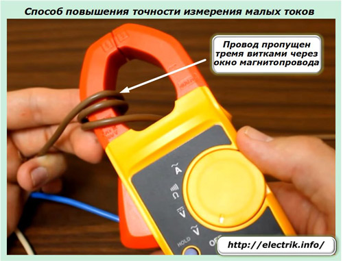
With conventional clamps, it can be difficult to determine the values \u200b\u200bof small currents due to the low sensitivity of the device. The way out of this situation is quite simple: pass the conductor with the measured current through the current clamp magnetic circuit several times, as shown in the photo above. In this case, the total magnetic flux increases in proportion to the number of turns and the indication on the display also increases. It remains only to divide the reading by the number of turns and get the exact value even for small currents. Please note that this technique is only suitable for working with flexible, insulated conductors. Voltage measurement methods The use of current clamps in the voltmeter mode, in principle, is no different from similar measurements with other devices.
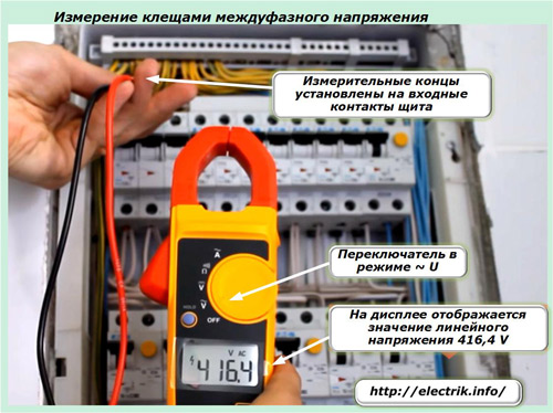
The removable ends of the conductors are installed in the sockets of the flares, which are previously switched to the voltage measurement mode by switches. The second ends of the insulated wires are applied to the potential terminals and the reading is taken on the display, as shown in the photo above. Features of measurement of resistance, frequency. temperature Ways to measure power consumption Current clamps do not have a direct method for measuring and reading power, but they can perform this operation indirectly. To do this, you need to determine the methods described above: load current; We can conclude that the power consumption is two kilowatts. Checking the absence of foreign consumers Using current clamps, you can check for unauthorized connection of consumers to the power cable. To do this, it is enough to install the clamps on the input shield in the load measurement mode and, leaving the normal power on, turn off all the lamps and release all the sockets from the devices, that is, to ensure idling for the input cable. If the clamps in this case show a zero value, then there is no unauthorized connection and no leakage currents. Otherwise, it is necessary to carefully deal with the cause of the formation of such a load. 1. Any measuring device is intended for use under certain technical conditions and work with specific loads. These characteristics should be familiarized in advance and observed during operation. For example, for Fluke devices, the marking CAT III 600 V or CAT III 300 V is used. It indicates that the electrical circuit of the device is made with protection against short-term overvoltages in the measured network up to 600 or 300 volts, respectively. If the limit of the measured value is unknown, then the device is set to the maximum value mode. 2. Working insulation on the expandable magnetic circuit and measuring tips protects the user from creating unauthorized short circuits when working under voltage. It is necessary to monitor her condition. This situation is especially relevant when measuring currents on bare, bare wires. 3. Current clamps are measuring instruments. They must undergo periodic metrological verification in an electrical measuring laboratory and have its stamp on the case or a verification certificate, the validity of which is limited. 4. Since current clamps are used for work under voltage, a prerequisite for their safe operation is a periodic test of the insulation layer for strength in an electrical testing laboratory, drawing up a test report and affixing an appropriate stamp. Without passing the insulation test and verification, the use of clamps in work, even just purchased from the manufacturer, is prohibited by the rules. Damage may occur if the storage or transportation standards are violated. Pre-sale preparation of the tool in the store is not able to detect the defects that have arisen. 5. Before measuring resistances, make sure that there are no voltage potentials on them. They can not only affect the accuracy of readings, but also damage, burn sensitive measurement circuits by generating dangerous currents. 6. Working with current clamps under voltage is classified as dangerous to human life. Only trained and trained personnel with an electrical safety group of at least the third is allowed to it. |


New
- Duel (story), plot, heroes Kuprin duel read online summary
- The shortest retelling of "Scarlet Sails
- Rating of the best perfumes for women
- Top spirits. Spirit Rating. Other Factors Affecting Durability
- The largest meteorites that fell to Earth (22 photos) The fall of the meteorite recently
- Geysers mora top vega Operation and repair work
- How the son of Andrei Dementiev died
- Alexander Grinev Alexander Grinev married Buzov blog
- Why did the Hands Up group break up?
- How wives cheat on their husbands How to spot signs of a cheating wife in behavior


