Sections of the site
Editor's Choice:
- How to unlock ariston washing machine
- Pros and cons of LED lighting
- Pulse relay: device and connection
- How to calculate the illumination of a room with LED lamps?
- Plastic box - do-it-yourself aesthetic view of electrical wiring
- Electricity consumption of a warm floor: electric and film
- Installing a pump in a well: how to properly install pumping equipment
- Electrician Toolkit Overview
- How to choose a water heater: the most complete list of evaluation criteria
- 1 acoustics on the example of Sven SPS-860 and Realtek ALC889 codec
Advertising
| Continuity of the chain: we check the wires and individual elements of the circuit |
|
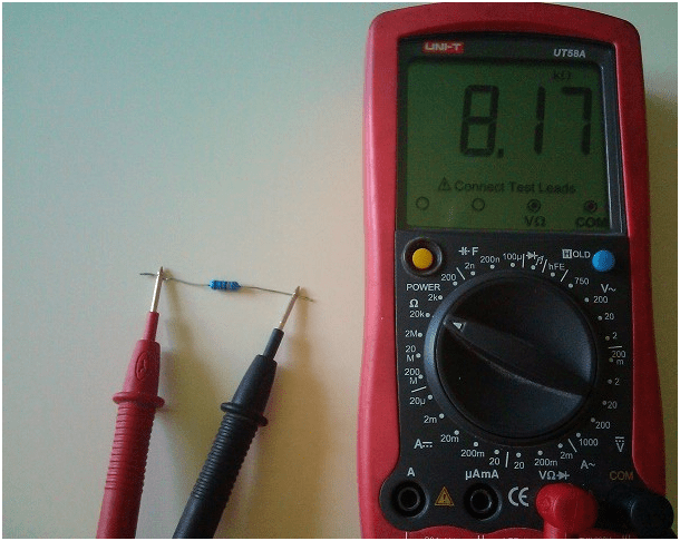
Tester, avometer, multimeter - these are the names of the same measuring instrument. It allows you to measure with acceptable accuracy the main electrical parameters - voltage, current and resistance. Information is displayed either on a pointer board, like in analog models of past years, or on a digital board, like in modern models. Regardless of the type of information display, a power source is installed in the tester. Usually these are two 1.5 V finger batteries. Any tester has at least two terminals to which probes are connected. They serve to connect the tester to two points of the electrical circuit whose parameters are being tested. Measurement of voltage and current does not require the consumption of batteries. But the so-called "ringing" is based on the creation of voltage and current between the touch points of the tester probes. Therefore, first of all, when ringing electrical circuits, batteries with sufficient energy are needed. This is a measurement of the resistance of an electrical circuit. And if it is not there, and the probes are in contact with each other, then the value of the measured resistance is zero. Therefore, if the readings on the display are different from zero, the tester must be calibrated with a regulator for adjustment. In this case, it is best to set the measurement range in Ohms. In this mode, the maximum battery consumption is obtained. If you can’t get a zero on the scoreboard, then they need to be replaced. In an analog device, you can remove the batteries and check them in current measurement mode. Usually one of them is discharged more than the other. Therefore, you can replace the most discharged battery with a fresh one and recheck the zero setting in the ohm resistance measurement range. If everything went well, you can start calling. Although if you do not need to measure any resistance values, checking the zero setting and the condition of the batteries is not necessary. When checking an electrical circuit, it is necessary to make sure that the electric current created by the tester flows only through this circuit. Otherwise, the scoreboard will display values that take into account neighboring circuits. This is possible, for example, in a printed circuit board. Therefore, it is possible to correctly check or measure the resistance of only one element installed in it and only with one output soldered from the board. Resistor continuityIf this element turns out to be a resistor with an unknown resistance, for example, color-coded, and the tester has several resistance measurement ranges, you can first set any resistance measurement range. Then touch the leads of the resistor with the probes and look at the scoreboard. If the tester is analog and the range is selected unsuccessfully, the arrow will be close to the extreme positions. In this case, you need to switch to another range, in which the arrow will be close to the middle of the scoreboard. After that, you need to refine the zero setting for this range and measure the resistance of the resistor. Approximately the same is done by ringing the resistor with a digital tester. The difference is only in the readings on the scoreboard in numbers and it may not be necessary to check the zero setting, since the digital testers have been upgraded.
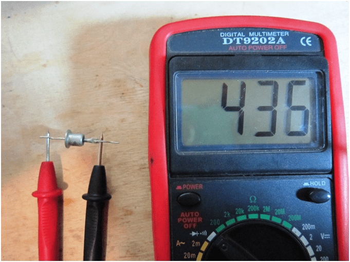
Diode continuityDiodes come in several varieties. They are united by the presence of only two conclusions. However, they perform different functions. For example, ringing a tunnel diode with a tester does not make sense, since it will simply be a resistance measurement without the possibility of checking its suitability for its purpose. The same applies to zener diodes and LEDs. They can be tested as intact, but still do not meet the parameters. Therefore, it is correct to test only rectifier diodes with a tester. In this case, it is possible to identify a faulty diode and determine the anode and cathode of a serviceable one. If, after touching the terminals in the kiloohm measurement mode, there are no readings on the display, and when the probes are swapped, the resistance reading appears on the display, the diode is working. In this case, the anode will correspond to the “plus” probe, and the cathode to the “minus” probe when reading on the scoreboard. The indications on the scoreboard, regardless of the change of probes in places, indicate that the diode is damaged. But this is true only with full confidence that this is a rectifier diode. Otherwise, it may be a working zener diode or a tunnel diode. The same can be true when showing a break on the scoreboard. That is, with indications on the display of very high resistance, at any position of the probes, only the rectifier diode can be faulty. Dinistor - a switching diode, switched on by a voltage of a certain value - can be serviceable.
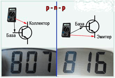
Transistor continuityThe tester is recommended to check only bipolar transistors. For FETs, the gate junction may be damaged during testing due to its high sensitivity to static electricity. To check, you will need to free the collector and emitter from the connections. Since transistors are sensitive to overheating when soldering, do not remove them from the board. It is better to break the electrical circuit by unsoldering one of the terminals of the diode or resistor connected to this transistor. All bipolar transistors have a collector, base and emitter, regardless of the design. If the transistor is working, the ringing of the base-emitter and base-collector junctions is obtained like two diodes with a common output. They are the base. In this case, the collector-emitter junction is usually in good condition and shows high resistance at any position of the probes. Therefore, it is necessary to find the base first. To do this, one probe must be connected to any output, and the other connected in turn to the remaining two. And while looking at the scoreboard. If the readings are significantly different, go to the next conclusion. If in this case the readings are different, you must go to the last conclusion. With different indications for all three conclusions, it is necessary to swap the probes in places and repeat the test. If it was not possible to find a terminal, relative to which the other two show almost the same resistance, then the transistor is not working. If it works, then the base is found. The positive probe on the base is an npn transistor. Negative - p-n-p transistor.
Capacitor continuityThe capacitor is also tested by the tester. You can check the condition of the insulation between the plates and evaluate the capacitance. But the latter is possible only for sufficiently large capacitance values, starting from units of microfarads. In this case, it is better to use a tester with an arrow display, since the movement of the arrow is much more noticeable than the rapid change of numbers. When ringing, a good capacitor shows a break in the megohm measurement range. But this does not apply to polar electrolytic capacitors. When checking them, polarity must be observed, touching the positive probe to the positive terminal, and the negative probe to the negative terminal of the capacitor. And at the same time, the display will show resistance. The bigger it is, the better. The lower the leakage current. If the measured resistance between the terminals is small and the display shows tens of kilo-ohms or less, the capacitor is damaged. When touching the terminals of a capacitor with a capacity of units of microfarads or more, the readings on the display begin with values close to zero and then increase. This is due to the filling of the electrical capacity with the energy of the tester batteries. At the same time, it is a source of EMF with a certain internal resistance. It is minimal when using the ohm range and increases as you switch ranges further. Therefore, for a particular capacitor, it is necessary to choose the optimal resistance measurement range. Then you can compare several capacitors in terms of capacitance. A slower movement of the arrow corresponds to a larger capacitance value.
The tester is indispensable for evaluating electrical circuits of one or more elements. But you should not leave the tester in the same state after such checks. You must either turn it off or switch it to current or voltage measurement mode. This will prolong the life of its batteries. |


New
- Kievan Rus: education and history
- What vitamins are good for facial skin?
- Rudbeckia is spinous. Rudbeckia is a perennial. flower planting technology
- Secrets of losing weight by Ksenia Borodina What pills did Ksenia Borodina take for weight loss
- Kuriles: history with geography History of the disputed Kuril Islands
- Beer styles: porter and stout, lager and ale
- The optimal temperature for each stage of the distillation of moonshine and mash
- Rye malt and what can be done with it?
- How to make fortified wine at home
- How to make wine yeast at home, instructions for use


