Sections of the site
Editor's Choice:
- How to unlock ariston washing machine
- Pros and cons of LED lighting
- Pulse relay: device and connection
- How to calculate the illumination of a room with LED lamps?
- Plastic box - do-it-yourself aesthetic view of electrical wiring
- Electricity consumption of a warm floor: electric and film
- Installing a pump in a well: how to properly install pumping equipment
- Electrician Toolkit Overview
- How to choose a water heater: the most complete list of evaluation criteria
- 1 acoustics on the example of Sven SPS-860 and Realtek ALC889 codec
Advertising
| Do-it-yourself wiring wiring: from a diagram to installation |
|
Even 15 - 20 years ago, the load on the power grid was relatively small, but today the presence of a large number of household appliances has provoked an increase in loads at times. Old wires are far from always able to withstand heavy loads and over time there is a need to replace them. Laying electrical wiring in a house or apartment is a matter that requires certain knowledge and skills from the master. First of all, this concerns knowledge of the rules for wiring electrical wiring, the ability to read and create wiring diagrams, as well as skills in electrical installation. Of course, you can do the wiring with your own hands, but for this you must adhere to the rules and recommendations below. Wiring RulesAll construction activities and building materials are strictly regulated by a set of rules and requirements - SNiP and GOST. As for the installation of electrical wiring and everything related to electricity, you should pay attention to the Rules for the Arrangement of Electrical Installations (abbreviated PUE). This document prescribes what and how to do when working with electrical equipment. And if we want to lay electrical wiring, then we will need to study it, especially the part that relates to the installation and selection of electrical equipment. The following are the basic rules that should be followed when installing electrical wiring in a house or apartment:
Project and wiring diagramWork on laying electrical wiring begins with the creation of a project and a wiring diagram. This document is the basis for future house wiring. Creating a project and a scheme is quite a serious matter and it is better to entrust it to experienced professionals. The reason is simple - the safety of those living in a house or apartment depends on it. Project creation services will cost a certain amount, but it's worth it.
Those who are used to doing everything with their own hands will have to, adhering to the rules described above, as well as having studied the basics of electrics, independently make a drawing and calculations for the loads on the network. There are no particular difficulties in this, especially if there is at least some understanding of what electric current is, and what are the consequences of careless handling of it. The first thing you need is the symbols. They are shown in the photo below:
Using them, we make a drawing of the apartment and outline lighting points, installation locations for switches and sockets. How many and where they are installed is described above in the rules. The main task of such a scheme is to indicate the installation location of devices and wires. When creating a wiring diagram, it is important to think in advance where, how much and what household appliances will be. The next step in creating the circuit will be the wiring to the connection points on the circuit. At this point it is necessary to dwell in more detail. The reason is the type of wiring and connection. There are several such types - parallel, serial and mixed. The latter is the most attractive due to the economical use of materials and maximum efficiency. To facilitate the laying of wires, all connection points are divided into several groups:
The above example is just one of many lighting group options. The main thing to understand is that if you group the connection points, the amount of materials used is reduced and the circuit itself is simplified.
Also in the wiring project, the calculation of the estimated current strength in the network and the materials used are indicated. The calculation is performed according to the formula: I=P/U; where P is the total power of all devices used (Watts), U is the mains voltage (Volts). For example, a 2 kW kettle, 10 60 W bulbs, a 1 kW microwave, a 400 W refrigerator. Current strength 220 volts. As a result (2000+(10x60)+1000+400)/220=16.5 Amps. In practice, the current strength in the network for modern apartments rarely exceeds 25 A. Based on this, all materials are selected. First of all, this concerns the cross section of the wiring. To facilitate the selection, the table below shows the main parameters of the wire and cable:
The table shows the most accurate values, and since the current can fluctuate quite often, a small margin is required for the wire or cable itself. Therefore, all wiring in an apartment or house is recommended to be made of the following materials:
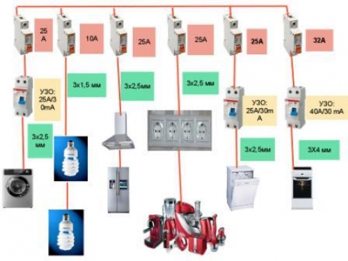
To find out the exact length of the wire, you will have to run a little around the house with a tape measure, and add another 3-4 meters of stock to the result. All wires are connected to the lighting panel, which is installed at the entrance. Protection circuit breakers are mounted in the shield. Usually this is an RCD for 16 A and 20 A. The former are used for lighting and switches, the latter for sockets. For an electric stove, a separate RCD is installed at 32 A, but if the power of the stove exceeds 7 kW, then an RCD is installed at 63 A.
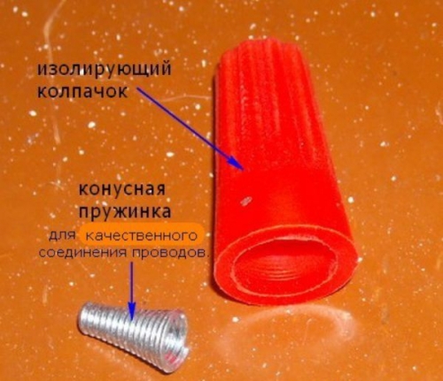
Now you need to calculate how many sockets and distribution boxes you need. Everything is pretty simple here. Just look at the diagram and make a simple calculation. In addition to the materials described above, various consumables will be required, such as electrical tape and PPE caps for connecting wires, as well as pipes, cable channels or boxes for electrical wiring, socket boxes. Installation of electrical wiringThere is nothing super complicated in the work on the installation of electrical wiring. The main thing during installation is to follow the safety rules and follow the instructions. All work can be done alone. From the installation tool, you will need a tester, a puncher or a grinder, a drill or a screwdriver, wire cutters, pliers and a Phillips and slotted screwdriver. A laser level would be helpful. Since without it it is quite difficult to make vertical and horizontal markings.
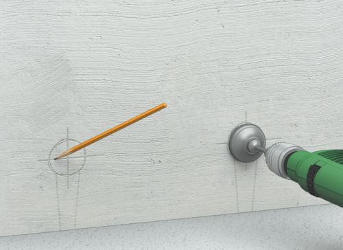
Marking and preparation of channels for electrical wiring
We start installation with markup. To do this, using a marker or pencil, we put a mark on the wall where the wire will be laid. At the same time, we observe the rules for placing wires. The next step is to mark the places for the installation of lighting fixtures, sockets and switches and a lighting panel.
Having finished with the markup, we proceed either to the installation of wiring in an open way, or to the chasing of walls for hidden wiring. First, with the help of a perforator and a special nozzle of the crown, holes are cut out for the installation of sockets, switches and junction boxes. For the wires themselves, strobes are made using a grinder or a puncher. In any case, there will be a lot of dust and dirt. The depth of the groove of the strobe should be about 20 mm, and the width should be such that all wires fit freely into the strobe.
As for the ceiling, there are several options for resolving the issue with the placement and fixing of the wiring. The first - if the ceiling is suspended or suspended, then all the wiring is simply fixed to the ceiling. The second - a shallow strobe is made for wiring. The third - the wiring is hidden in the ceiling. The first two options are extremely simple to implement. But for the third, some explanations will have to be made. In panel houses, ceilings with internal voids are used, it is enough to make two holes and stretch the wires inside the ceiling. Having finished with the gating, we proceed to the last stage of preparation for wiring. Wires to bring them into the room must be pulled through the walls. Therefore, you will have to punch holes with a puncher. Usually such holes are made in the corner of the premises. We also make a hole for the wire plant from the switchboard to the lighting panel. Having finished the wall chasing, we begin the installation. Installation of open wiring
We begin installation with the installation of a lighting panel. If a special niche was created for it, then we place it there, if not, then we simply hang it on the wall. We install an RCD inside the shield. Their number depends on the number of lighting groups. The shield assembled and ready for connection looks like this: in the upper part there are zero terminals, grounding terminals at the bottom, automatic machines are installed between the terminals.
Now we start the wire VVG-5 * 6 or VVG-2 * 6 inside. From the side of the switchboard, the electric wiring is connected by an electrician, so for now we will leave it without connection. Inside the lighting panel, the input wire is connected as follows: we connect the blue wire to zero, the white wire to the top contact of the RCD, and connect the yellow wire with a green stripe to ground. RCD automata are interconnected in series at the top using a jumper from a white wire. Now let's move on to the wiring in an open way.
On the lines outlined earlier, we fix boxes or cable channels for electrical wiring. Often, with open wiring, they try to place the cable channels themselves near the plinth, or vice versa, almost under the very ceiling. We fix the wiring box with self-tapping screws in increments of 50 cm. We make the first and last hole in the box at a distance of 5 - 10 cm from the edge. To do this, we drill holes in the wall with a puncher, hammer the dowel inside and fix the cable channel with self-tapping screws. Another distinctive feature of open wiring are sockets, switches and distribution boxes. All of them are hung on the wall, instead of being walled in. Therefore, the next step is to install them in place. It is enough to attach them to the wall, mark the places for fasteners, drill holes and fix them in place.
Next, we proceed to the wiring. We start by laying the main line and from the sockets to the lighting panel. As already noted, we use the VVG-3 * 2.5 wire for this. For convenience, we start from the connection point towards the shield. We hang a label on the end of the wire indicating what kind of wire and where it comes from. Next, we lay the wires VVG-3 * 1.5 from switches and lighting fixtures to junction boxes.
Inside the junction boxes, we connect the wires using PPE or carefully insulate them. Inside the lighting panel, the main wire VVG-3 * 2.5 is connected as follows: brown or red wire - phase, connected to the bottom of the RCD, blue - zero, connected to the zero bus at the top, yellow with a green stripe - ground to the bus at the bottom. With the help of a tester, we “ring” all the wires in order to eliminate possible errors. If everything is in order, we call an electrician and connect to the switchboard. Installation of hidden electrical wiringHidden wiring is quite simple. A significant difference from the open one is only in the way the wires are hidden from the eyes. The rest of the steps are almost the same. First, we install a lighting shield and RCDs, after which we start and connect the input cable from the side of the switchboard. We also leave it unconnected. This will be done by an electrician. Next, we install distribution boxes and socket boxes inside the niches made.
Now let's move on to the wiring. We are the first to lay the main line from the VVG-3 * 2.5 wire. If it was planned, then we lay the wires to the sockets in the floor. To do this, we put the VVG-3 * 2.5 wire into a pipe for electrical wiring or a special corrugation and lay it to the point where the wire is output to the sockets. There we place the wire inside the strobe and put it into the socket. The next step will be laying the VVG-3 * 1.5 wire from switches and lighting points to junction boxes, where they are connected to the main wire. We isolate all connections with PPE or electrical tape.
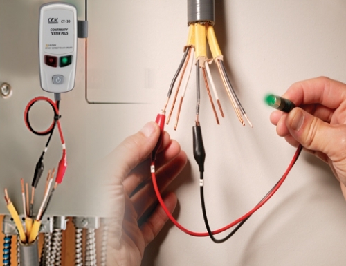
At the end, we “ring” the entire network with the help of a tester for possible errors and connect it to the lighting panel. The connection method is similar to that described for open wiring. Upon completion, we close the strobes with gypsum putty and invite an electrician to connect it to the switchboard. Laying electricians in a house or apartment for an experienced craftsman is quite an easy task. But for those who are not well versed in electrics, you should take the help of experienced professionals from start to finish. This, of course, will cost money, but this way you can protect yourself from mistakes that can lead to a fire. |


New
- Rye malt and what can be done with it?
- How to make fortified wine at home
- How to speed up the fermentation process of homemade wine
- How to make wine yeast at home, instructions for use
- Unfiltered beer - a source of good mood and nutrients Wheat or barley beer
- Intoxicated sweets: seven recipes for berry tinctures
- Dessert wines: names
- Diesel heating boilers for a private house
- Analysis "in a bad society" Korolenko In a bad society reduction
- Fuel consumption of diesel heating boiler


