Sections of the site
Editor's Choice:
- How to unlock ariston washing machine
- Pros and cons of LED lighting
- Pulse relay: device and connection
- How to calculate the illumination of a room with LED lamps?
- Plastic box - do-it-yourself aesthetic view of electrical wiring
- Electricity consumption of a warm floor: electric and film
- Installing a pump in a well: how to properly install pumping equipment
- Electrician Toolkit Overview
- How to choose a water heater: the most complete list of evaluation criteria
- 1 acoustics on the example of Sven SPS-860 and Realtek ALC889 codec
Advertising
| Motion sensor repair. Detailed analysis |
|
, which caused a heated discussion and many questions. Well, since there are a lot of questions about the repair of motion sensors, I decided to put them in a separate article-continuation.
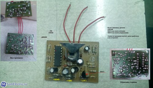
There are many motion sensor circuits, but the principle is the same. This principle and much more regarding this device is given at the link at the beginning of the article, once again I recommend studying it and comments on it. The same article provides links to other articles about motion sensors, you can download instructions and datasheets for the details of the sensor's electrical circuit. So, I will give the most popular motion sensor circuit once again: This scheme was sent by my regular reader Alexander from Korolev in December 2014, for which many thanks to him again. I will rely on this scheme in the text of the article, since it is the most typical. It should not be confusing that the circuit in our example will be scattered over two boards - low-current and power.
Now I am publishing a photo of the motion sensor boards, which were sent by my other reader - Renat.
Low current motion sensor board
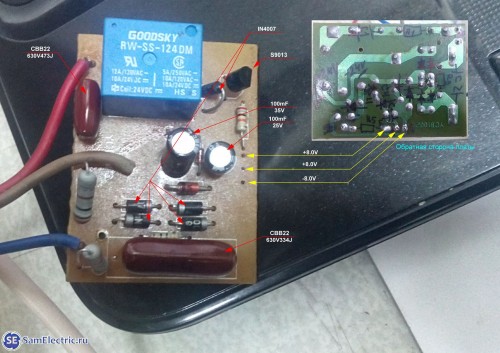
Power board (power) motion sensor Here is our correspondence with Renat: Renat: Hello! According to the diagram and description, I have the same sensor, I don’t know the exact model, they asked me to look at “stopped working”. Stopped at the power board. I checked all the elements, after the diode bridge + 24V comes out, the zener diode gives out + 8V, soldered the second part of the circuit (the board where the IR receiver, microcircuit, etc.). And now, I can not understand why the relay is activated when I apply voltage? 
|

New
- Kievan Rus: education and history
- What vitamins are good for facial skin?
- Rudbeckia is spinous. Rudbeckia is a perennial. flower planting technology
- Secrets of losing weight by Ksenia Borodina What pills did Ksenia Borodina take for weight loss
- Kuriles: history with geography History of the disputed Kuril Islands
- Beer styles: porter and stout, lager and ale
- The optimal temperature for each stage of the distillation of moonshine and mash
- Rye malt and what can be done with it?
- How to make fortified wine at home
- How to make wine yeast at home, instructions for use


