Sections of the site
Editor's Choice:
- How to unlock ariston washing machine
- Pros and cons of LED lighting
- Pulse relay: device and connection
- How to calculate the illumination of a room with LED lamps?
- Plastic box - do-it-yourself aesthetic view of electrical wiring
- Electricity consumption of a warm floor: electric and film
- Installing a pump in a well: how to properly install pumping equipment
- Electrician Toolkit Overview
- How to choose a water heater: the most complete list of evaluation criteria
- 1 acoustics on the example of Sven SPS-860 and Realtek ALC889 codec
Advertising
| Electricity transmission scheme without wires |
|
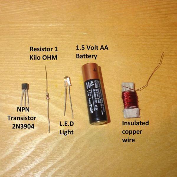
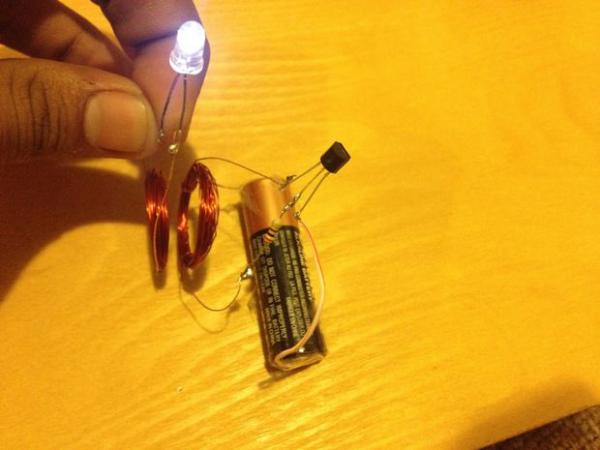
This is a simple circuit that can power a light bulb without any wires, at a distance of almost 2.5 cm! This circuit acts as both a boost converter and a wireless power transmitter and receiver. It is very easy to make and, if perfected, can be used in a variety of ways. So let's get started! Step 1. Necessary materials and tools.
Required tools: 1) Scissors or a knife. 2) Soldering iron (Optional). If you do not have a soldering iron, you can simply twist the wires. I did this when I didn't have a soldering iron. If you would like to try the circuit without soldering, you are most welcome. 3) Lighter (Optional). We will use a lighter to burn off the insulation on the wire and then use scissors or a knife to scrape off the remaining insulation. Step 2: Watch the video to see how. Step 3: Brief repetition of all steps. So, first of all you have to take the wires, and make a coil by winding 30 turns around a round cylindrical object. Let's call this coil A. With the same round object, start making the second coil. After winding the 15th turn, create a branch in the form of a loop from the wire and then wind another 15 turns on the coil. So now you have a coil with two ends and one branch. Let's call this coil B. Tie knots at the ends of the wires so they don't unwind on their own. Burn the insulation on the ends of the wires and on the branch on both coils. You can also use scissors or a knife to strip the insulation. Make sure that the diameters and number of turns of both coils are equal! Build the Transmitter: Take the transistor and place it with the flat side facing up and facing you. The pin on the left will be connected to the emitter, the middle pin will be the base pin, and the pin on the right will be connected to the collector. Take a resistor and connect one of its ends to the base terminal of the transistor. Take the other end of the resistor and connect it to one end (not the tap) of Coil B. Take the other end of Coil B and connect it to the collector of the transistor. If you like, you can connect a small piece of wire to the emitter of the transistor (This will work as an extension of the Emitter.) Set up the receiver. To create a receiver, take Coil A and attach its ends to different pins on your LED. You've got the blueprint! Step 4: Schematic diagram.
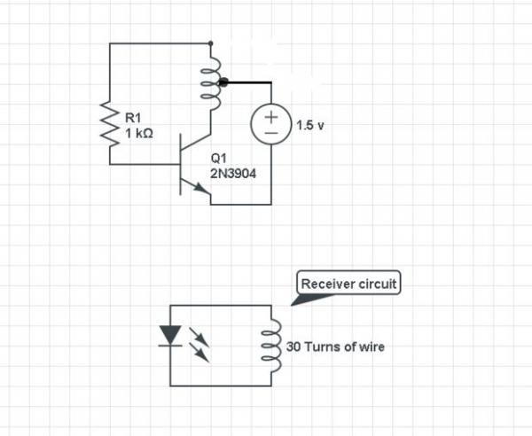
Here we see the schematic diagram of our connection. If you don't know some symbols on the diagram, don't worry. The following pictures show everything. Step 5. Drawing of circuit connections.
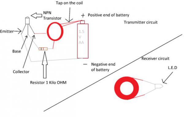
Here we see an explanatory drawing of the connections of our circuit. Step 6. Using the scheme.
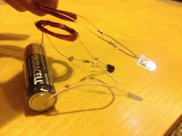
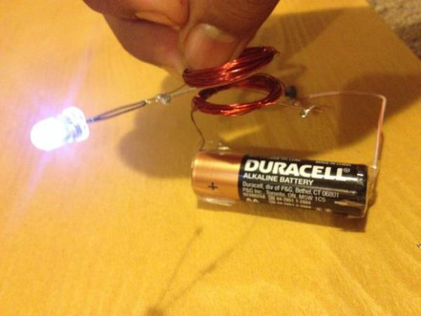
Simply take a branch of Coil B and connect it to the positive end of the battery. Connect the negative pole of the battery to the emitter of the transistor. Now if you bring the LED coil close to coil B, the LED lights up! Step 7. How is this scientifically explained? (I will just try to explain the science of this phenomenon in simple words and analogies, and I know that I can be wrong. In order to properly explain this phenomenon, I will have to go into all the details, which I am not able to do, so I just want to generalize analogies to explain the scheme). The transmitter circuit we just created is the Oscillator circuit. You may have heard of the so-called Joule Thief circuit, and it bears a striking resemblance to the circuit we created. The Joule Thief circuit takes power from a 1.5 volt battery, outputs power at a higher voltage, but with thousands of intervals between them. The LED only needs 3 volts to light up, but in this circuit it may well light up with a 1.5 volt battery. So the Joule Thief circuit is known as a voltage boost converter and also as an emitter. The circuit we created is also an emitter and a voltage boost converter. But the question may arise: "How to light an LED from a distance?" This is due to induction. To do this, you can, for example, use a transformer. A standard transformer has a core on both sides. Assume that the wire on each side of the transformer is equal in size. When an electric current passes through one coil, the transformer coils become electromagnets. If an alternating current flows through the coil, then the voltage fluctuations occur along a sinusoid. Therefore, when an alternating current flows through the coil, the wire takes on the properties of an electromagnet, and then loses electromagnetism again when the voltage drops. The coil of wire becomes an electromagnet and then loses its electromagnetic characteristics at the same speed as the magnet moves out of the second coil. When the magnet moves quickly through the coil of wire, electricity is generated, so the oscillating voltage of one coil on the transformer induces electricity in the other coil of wire, and electricity is transferred from one coil to another without wires. In our circuit, the core of the coil is air, and an AC voltage passes through the first coil, thus causing voltage in the second coil and lighting the bulbs!! Step 8. Benefits and tips for improvement. So in our circuit, we just used an LED to show the effect of the circuit. But we could do more! The receiver circuit gets its electricity from AC, so we could use it to light up fluorescent lights! Also, with our scheme, you can do interesting magic tricks, funny gifts, etc. To maximize the results, you can experiment with the diameter of the coils and the number of revolutions on the coils. You can also try flattening the coils and see what happens! The possibilities are endless!! Step 9. Reasons why the scheme may not work. What problems you may encounter and how you can fix them:
Solution: Did you use the right sized resistor? I didn't use the resistor the first time and the transistor started to smoke. If that doesn't help, try using heat shrink or use a higher grade transistor.
Solution: There could be many reasons. First, check all connections. I accidentally changed the base and collector in my connection and it became a big problem for me. So, check all connections first. If you have a device such as a multimeter, you can use it to check all connections. Also make sure that both coils are the same diameter. Check if there is a short circuit in your network. I am not aware of any other problems. But if you still encounter them, let me know! I'll try to help in any way I can. Also, I'm a grade 9 student and my scientific knowledge is extremely limited, so if you find any mistakes in me, please let me know. Suggestions for improvement are more than welcome. Good luck with your project! |

New
- Rye malt and what can be done with it?
- How to make fortified wine at home
- How to speed up the fermentation process of homemade wine
- How to make wine yeast at home, instructions for use
- Unfiltered beer - a source of good mood and nutrients Wheat or barley beer
- Intoxicated sweets: seven recipes for berry tinctures
- Dessert wines: names
- Diesel heating boilers for a private house
- Analysis "in a bad society" Korolenko In a bad society reduction
- Fuel consumption of diesel heating boiler


