A clamp meter is a must have for every electrician.
Planning to do your own electrical work? To do this, you will need an AC current clamp that allows you to make all the necessary measurements in your home electrical wiring. I will tell you how they are arranged and what they are for, and I will also describe in detail how to work with this device correctly.
What can measuring clamps be used for?
Modern clamp meters, in fact, can be considered a multimeter. This tool allows you to measure not only the current strength, but also determine many other parameters of the electrical network:
The presence or absence of a phase in the network;
Voltage of direct and alternating current;
Electrical circuit resistance;
Resistance and breakdown of insulation of electrical appliances;
Open or short circuit in the electrical circuit;
Power consumption of electrical appliances;
The actual load on the supply cable or on the introductory machine in the electrical panel.
Induction clamp meters for measuring current allow you to measure even on an insulated conductor without breaking the electrical circuit. The main condition is that only one conductor must pass through the frame of the magnetic circuit - either phase or zero.
Varieties of current clamps
To know which current clamps to choose for your home workshop, you must understand that they differ from each other not only in appearance. Different models may have significant functional differences, for example:
Indicator- can be analog or digital:
In analog indicators, readings are displayed on pointer instruments. Such devices are cheaper, but they are less convenient because they have less functionality;
Digital indicators display information in a more convenient way, but they cost a little more, and they definitely require a battery to work.
Measurement parameters:
The simplest models can only measure current in an AC voltage network;
Devices from the middle price range allow you to measure the voltage and strength of alternating and direct current, as well as resistance and short circuit in an electrical circuit;
More expensive models, in addition to basic measurements, may have a number of additional functions, for example, a digital thermometer with an external temperature sensor, a tester for diodes and transistors, etc.
Current clamp device
Usually clamps for measuring current strength are made in a plastic case and are sold in a soft cloth case. The package also includes an instruction manual and wires with plastic tips, and batteries must be purchased separately.
Clamps for measuring current strength consist of the following elements:
Magnetic core made of metal in a plastic shell in the form of hinged closing pincers;
Reveal keyflaps of the magnetic circuit. It is pressed to pass the current-carrying cable through the magnetic circuit;
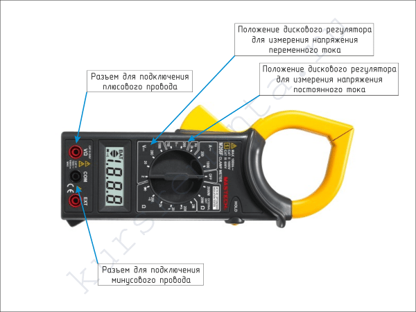
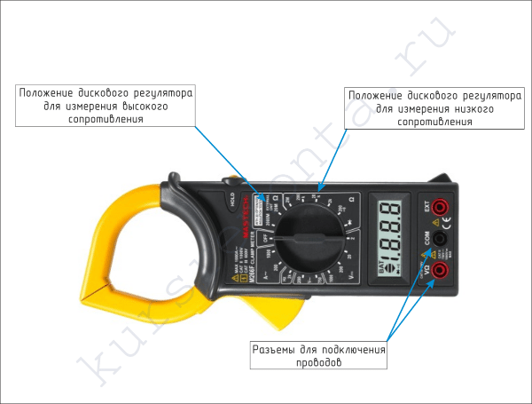
Plug connectors- are used to connect wires with measuring probes. The black connector is common, and the red ones are used depending on the type of measurement;
Disc switch- used to select measurement modes;
LCD screen- serves to output digital information. Some models are equipped with backlit screens;
Key for fixing measurement results in the device memory. It is used when during measurements you do not see the readings on the digital indicator. After clicking, they remain on the screen;
Wires with plastic measuring probes. They are used to measure resistance, direct and alternating voltage, as well as other parameters of the electrical network;
DC source(AA batteries or krone);
Cloth cover– used for storage and transportation of the device.
Principle of operation
All such devices for measuring alternating current work on the principle of a transformer with one winding, and the function of the magnetic circuit in it is performed by a detachable clamp frame:
Primary winding this transformer is a current-carrying bus or electric cable on which you measure the current strength;
Secondary winding located inside the device. It is wound with a thin wire with a large number of turns around the detachable frame of the magnetic circuit;
Ammeter- an indicator device that directly shows the value of the current strength:
In analog devices, the pointer ammeter is connected in series to the secondary winding of the transformer;
In digital devices, the signal from the secondary winding enters the electronic converter, which calculates and displays the current value on the liquid crystal screen.
AC current measurement performed according to the principle of electromagnetic induction:
During measurements, the current-carrying conductor must be inside the closed frame of the magnetic circuit;
When an alternating electric current passes through a conductor, an inductive voltage is induced in the magnetic circuit;
Due to electromagnetic induction, the electric current passes into the secondary winding, in which its strength is measured by an ammeter.
The principle of electromagnetic induction can only be used to measure the strength of alternating current. All other parameters of the electrical network are measured using wires with remote insulated probes.
How to use ticks correctly
Below is an illustrated instruction for use. In it, I will tell you how to properly use current clamps to measure basic parameters and determine faults in a household electrical network:
Illustration
Type of measurement
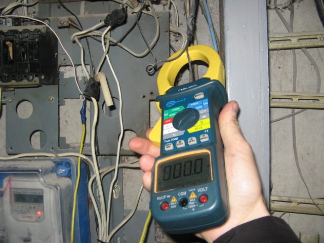
AC current measurement:
Turn the rotary control to the position with the alternating current (AC) icon;
Using the key, open the frame of the magnetic circuit, insert one conductor into it, and close it back;
The current value will be displayed on the screen;
For the correct display of information, it is advisable to keep the current clamps motionless and not move along the conductor;
To fix the readings, press the HOLD button;
Wires with probes in this case are not required.
DC current measurement:
Connect the wire with the red probe to the red connector, and the black wire to the black connector;
Set the dial in front of the designation of direct current (DC);
Connect wires with probes to the electrical circuit in series with the load;
After power is supplied to the load circuit, the device will display the consumed current on the screen.
When measuring current strength, parallel connection of the device to the network is strictly unacceptable!
Voltage measurement:
Connect wires with probes to the device as indicated above;
Set the regulator dial opposite the AC or DC voltage icon (V ~) or (V -);
Connect the probes on the wires to the network in parallel with the phase and neutral conductors;
To measure DC voltage, polarity must be observed;
The red probe must be connected to the positive conductor, and the black probe to the negative conductor.
To measure voltage, only the parallel connection of the device to the mains is always used.
Resistance measurement:
Use the dial on the tester to set the expected resistance value;
Low resistance is measured in ohms, and high resistance is measured in kiloohms or megaohms;
Touch the probes to each output of the electrical appliance;
If the indicator shows one, then you need to move the disk to a larger value.
Resistance is always measured in parallel with the load, and the polarity of the wires does not matter.
Detection of an open or short circuit:
The ringing of the circuit is performed by analogy with measuring resistance;
The regulator must be set to the position with the designation of the diode;
If the circuit has a very low resistance or a short circuit, you will hear a continuous beep from the built-in buzzer, and zero will appear on the screen;
If there is an open in the circuit, or it has a high resistance, then you will not hear anything, and a unit will be displayed on the indicator screen.
Determination of power consumption.
If you have a suspicion that one of the neighbors has connected to your cable, then it is easy to check it yourself:
Turn on several powerful consumers of electricity in your apartment;
With the help of clamps, measure the consumed current;
According to the formula P = IxV determine the power consumption;
For example, if the value of the consumed current is 20A, then the power consumption will be 20 x 220 = 4.4 kW / h;
Write down the current readings of the electric meter, and see how much they change within an hour;
If the consumption on the meter shows more than 4.4 kW / h, then you either have a voltage leak somewhere, or someone is stealing electricity from you.
If you need to take measurements in a circuit with a very small current strength, I advise you to do this: wind five or ten turns of a current-carrying conductor around the frame of the magnetic circuit and measure the current strength. The resulting value on the indicator must be divided by the number of turns (5 or 10).
Conclusion
Now you know how to choose current clamps, and how to use them correctly when performing electrical work. I advise you to pay attention to the video in this article, and leave all suggestions and questions to me in the comments.