To write this text, I was prompted by the feeling of ignorance by many of the principles of operation, the use (or even ignorance of the existence) of parallel protection against surge surges in the network, including those caused by lightning discharges Impulse noise in the network is quite common, they can occur during a thunderstorm, when powerful loads are turned on / off (since the network is an RLC circuit, fluctuations occur in it, causing voltage surges) and many other factors. In low-current, including digital circuits, this is even more relevant, since switching noise penetrates quite well through power sources (flyback converters are the most protected - in them the transformer energy is transferred to the load when the primary winding is disconnected from the network). In Europe, it has long been de facto obligatory to install surge protection modules (hereinafter, for simplicity, I will call lightning protection or SPD), although their networks are better than ours, and there are fewer thunderstorm areas. The use of SPDs has become especially relevant for the last 20 years, when scientists began to develop more and more options for field-effect MOSFET transistors, which are very afraid of exceeding the reverse voltage. And such transistors are used in almost all switching power supplies up to 1 kVA, as keys on the primary (network) side. Another aspect of the application of SPDs is to provide voltage limitation between the neutral and earth conductors. An overvoltage on the neutral conductor in the network can occur, for example, when switching the Transfer Switch with a separated neutral. During switching, the neutral conductor will be "in the air" and anything can be on it.
Characteristics of surge impulses
Overvoltage impulses in the network are characterized by the waveform and current amplitude. The shape of the current pulse is characterized by the time of its rise and fall - for European standards, these are pulses of 10/350 µs and 8/20 µs. In Russia, as often happens recently, they adopted European standards and GOST R 51992-2002 appeared. The numbers in the pulse shape designation mean the following: - the first one is the time (in microseconds) of current pulse rise from 10% to 90% of the maximum current value; - the second is the time (in microseconds) of the current pulse decay to 50% of the maximum current value;
Protective devices are divided into classes depending on the impulse power they can dissipate: 1) Class 0 (A) - external lightning protection (not considered in this post); 2) Class I (B) - protection against overvoltages characterized by impulse currents with an amplitude of 25 to 100 kA with a waveform of 10/350 μs (protection in the building's input distribution boards); 3) Class II (C) - protection against overvoltage, characterized by impulse currents with an amplitude of 10 to 40 kA with a waveform of 8/20 μs (protection in floor boards, electrical boards of premises, inputs of power supply equipment); 3) Class III (D) - protection against surges characterized by surge currents with an amplitude of up to 10 kA and a waveform of 8/20 μs (in most cases, protection is built into the equipment - if it is manufactured in accordance with GOST);
Surge protection devices
The main two SPD devices are arresters and varistors of various designs.
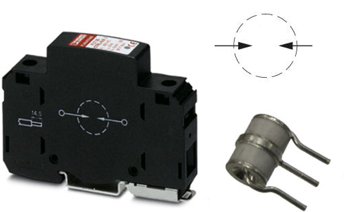
Discharger
A spark gap is an electrical device of an open (air) or closed (filled with inert gases) type, containing in the simplest case two electrodes. When the voltage on the electrodes of the arrester exceeds a certain value, it "breaks through", thereby limiting the voltage on the electrodes at a certain level. When a spark gap breaks down, a significant current (from hundreds of amperes to tens of kiloamperes) flows through it in a short time (up to hundreds of microseconds). After removing the overvoltage pulse, if the power that the arrester is capable of dissipating has not been exceeded, it goes into the initial closed state until the next pulse.
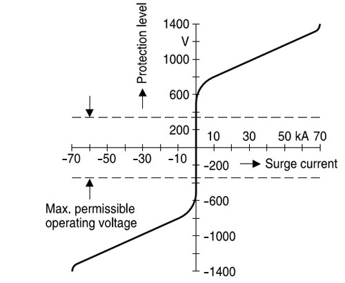
The main characteristics of arresters: 1) Protection class (see above); 2) Rated operating voltage - continuous operating voltage of the arrester recommended by the manufacturer; 3) Maximum operating alternating voltage - the limiting long-term voltage of the arrester, at which it is guaranteed not to work; 4) Maximum pulsed discharge current (10/350) µs - the maximum value of the current amplitude with a waveform (10/350) µs, at which the arrester will not fail and provide voltage limitation at a given level; 5) Rated pulsed discharge current (8/20) µs - nominal value of the current amplitude with a waveform (8/20) µs, at which the arrester will provide voltage limitation at a given level; 6) Limiting voltage - the maximum voltage on the electrodes of the arrester during its breakdown due to the occurrence of an overvoltage pulse; 7) Response time - the time of opening the arrester (for almost all arresters - less than 100 ns); 8) (rarely indicated by manufacturers) static voltage of the arrester breakdown - static voltage (slowly changing in time), at which the arrester will open. It is measured by applying a constant voltage. In most cases, it is 20-30% higher than the maximum operating AC voltage reduced to DC (AC voltage times the root of 2);
The choice of a spark gap is a rather creative process with numerous “spitting at the ceiling” - after all, we do not know in advance the value of the current that will occur in the network ... When choosing a spark gap, you can be guided by the following rules: 1) When installing protection in introductory shields from overhead power lines or in areas where there are frequent thunderstorms, install arresters with a maximum discharge current (10/350) µs of at least 35 kA; 2) Choose the maximum continuous voltage slightly higher than the expected maximum mains voltage (otherwise, there is a possibility that at a high mains voltage, the arrester will open and fail due to overheating); 3) Choose arresters with the lowest possible limiting voltage (it is obligatory to follow rules 1 and 2). Typically, the limiting voltage of class I arresters is 2.5 to 5 kV; 4) Between the N and PE conductors, install arresters specially designed for this (manufacturers indicate that they are for connection to N-PE conductors). In addition, these arresters are characterized by lower operating voltages, typically around 250 V AC (no voltage between neutral and ground in normal mode) and a large discharge current - from 50 kA to 100 kA and more. 5) Connect the arresters to the network with conductors with a cross section of at least 10 mm2 (even if the network conductors have a smaller cross section) and as short as possible. For example, if a current of 40 kA occurs in a conductor with a length of 2 measures with a cross section of 4 mm2, about 350 V will fall on it (in the ideal case, without taking into account the inductance - and it plays a big role here). the limiting voltage will be equal to the sum of the limiting voltage of the arrester and the voltage drop on the conductor with a pulsed current (our 350 V). Thus, the protective properties deteriorate significantly. 6) If possible, install arresters in front of the introductory circuit breaker and always in front of the RCD (in this case, it is necessary to install a fuse with a characteristic gL for a current of 80-125 A in series with the arrester to ensure that the arrester is disconnected from the network when it fails). Since no one will allow you to install an SPD in front of the introductory machine, it is desirable that the machine be for a current of at least 80A with a response characteristic D. This will reduce the likelihood of false operation of the machine when the arrester is triggered. The installation of an SPD in front of the RCD is due to the low resistance of the RCD to impulse currents, in addition, when the N-PE arrester is triggered, the RCD will falsely trip. Also, it is advisable to install an SPD in front of the electricity meters (which, again, the power engineers will not allow to do)
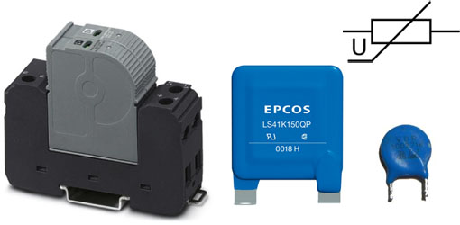
Varistor
Varistor - a semiconductor device with a "steep" symmetrical current-voltage characteristic.
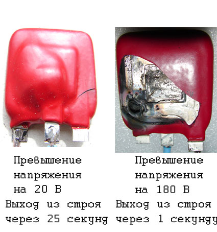
In the initial state, the varistor has a high internal resistance (from hundreds of kΩ to tens and hundreds of MΩ). When the voltage at the varistor contacts reaches a certain level, it sharply reduces its resistance and begins to conduct a significant current, while the voltage at the varistor contacts changes slightly. Like a spark gap, a varistor is capable of absorbing the energy of an overvoltage pulse lasting up to hundreds of microseconds. But with prolonged increased voltage, the varistor fails with the release of a large amount of heat (explodes). All DIN-rail varistors are equipped with thermal protection designed to disconnect the varistor from the mains if it is unacceptably overheated (in this case, it can be determined from the local mechanical indication that the varistor is out of order). In the photo, varistors with a built-in thermal relay after exceeding the operating voltage of different values. With a significant overvoltage, such a built-in thermal protection is practically ineffective - the varistors explode in such a way that it lays the ears. However, the built-in thermal protection in DIN-rail varistor modules is quite effective at any prolonged overvoltage, and manages to disconnect the varistor from the mains. A small video of naturalistic tests :) (supplying an increased voltage to a varistor with a diameter of 20 mm - an excess of 50 V)
Main characteristics of varistors: 1) Protection class (see above). Usually varistors have protection class II (C), III (D); 2) Rated operating voltage - continuous operating voltage of the varistor recommended by the manufacturer; 3) Maximum operating alternating voltage - the maximum long-term voltage of the varistor, at which it is guaranteed not to open; 4) Maximum pulse discharge current (8/20) µs - the maximum value of the current amplitude with a waveform (8/20) µs, at which the varistor will not fail and will provide voltage limitation at a given level; 5) Rated pulse discharge current (8/20) µs - nominal value of the current amplitude with a waveform (8/20) µs, at which the varistor will provide voltage limitation at a given level; 6) Limiting voltage - the maximum voltage on the varistor when it is opened due to the occurrence of an overvoltage pulse; 7) Operate time - varistor opening time (for almost all varistors - less than 25 ns); 8) (rarely indicated by manufacturers) varistor classification voltage - static voltage (slowly changing in time), at which the varistor leakage current reaches 1 mA. It is measured by applying a constant voltage. In most cases, it is 15-20% higher than the maximum operating AC voltage reduced to DC (AC voltage times the root of 2); 9) (a parameter very rarely indicated by manufacturers) the permissible error of the varistor parameters is ± 10% for almost all varistors. This error should be taken into account when choosing the maximum operating voltage of the varistor.
The choice of varistors, as well as arresters, is fraught with difficulties associated with the unknown conditions for their operation. When choosing a varistor protection, you can be guided by the following rules: 1) Varistors are installed as the second or third stage of surge protection; 2) When using class II varistor protection together with class I protection, it is necessary to take into account the different response speed of varistors and arresters. Since surge arresters are slower than varistors, if the SPD is not matched, the varistors will take on most of the overvoltage impulse and will quickly fail. To match I and II classes of lightning protection, special matching chokes are used (ultrasound manufacturers have their range for such cases), or the cable length between SPDs of classes I and II must be at least 10 meters. The disadvantage of this solution is the need for cutting chokes into the network or its lengthening, which increases its inductive component. The only exception is the German manufacturer PhoenixContact, which has developed special class I arresters with so-called "electronic ignition", which are "matched" to the varistor modules of the same manufacturer. These SPD combinations can be installed without additional approval; 3) Select the maximum continuous voltage slightly higher than the expected maximum mains voltage (otherwise, it is likely that at high mains voltage, the varistor will open and fail due to overheating). But here you can’t overdo it, since the varistor limiting voltage directly depends on the classification voltage (and, consequently, on the maximum operating voltage). An example of an unsuccessful choice of the maximum operating voltage is IEC varistor modules with a maximum continuous voltage of 440 V. If they are installed in a network with a rated voltage of 220 V, then its operation will be extremely inefficient. In addition, it should be taken into account that varistors tend to “age” (ie, over time, with many operations of the varistor, its classification voltage begins to decrease). Optimal for Russia will be the use of varistors with a long operating voltage of 320 to 350 V; 4) You need to choose with the least possible voltage limitation (in this case, the observance of rules 1 - 3 is mandatory). Usually the limiting voltage of class II varistors for mains voltage is from 900 V to 2.5 kV; 5) Do not connect varistors in parallel to increase the total power dissipation. Many manufacturers of SPD protection (especially class III (D)) sin by parallel connection of varistors. But, since 100% identical varistors do not exist (even from the same batch they are different), one of the varistors will always be the weakest link and will fail during an overvoltage pulse. With subsequent pulses, the rest of the varistors will fail, since they will no longer provide the required dissipation power (this is the same as connecting diodes in parallel to increase the total current - this cannot be done) 6) Connect varistors to the network with conductors with a cross section of at least 10 mm2 (even if the network conductors have a smaller cross section) and as short as possible (the reasoning is the same as for arresters). 7) If possible, install varistors before the introductory circuit breaker and always before the RCD. Since no one will allow installing an SPD in front of an introductory machine, it is desirable that the machine be for a current of at least 50A with a response characteristic D (for class II varistors). This will reduce the likelihood of false triggering of the machine when the varistor is triggered.
Brief overview of SPD manufacturers
Leading manufacturers specializing in SPDs for low-voltage networks are: Phoenix Contact; Dehn; OBO Bettermann; CITEL ; hakel. Also, many manufacturers of low-voltage equipment have SPD modules in their products (ABB, Schneider Electric, etc.). In addition, China is successfully copying SPDs from global manufacturers (since the Varistor is a fairly simple device, Chinese manufacturers produce quite high-quality products - for example, TYCOTIU modules). In addition, there are quite a few ready-made surge protection panels on the market, including modules of one or two protection classes, as well as fuses to ensure safety in case of failure of protective elements. In this case, the shield is fixed to the wall and connected to the existing electrical wiring in accordance with the manufacturer's recommendations. The cost of SPD varies depending on the manufacturer at times. At one time (several years ago), I conducted a market analysis and selected a number of manufacturers of protection class II (some were not included in the list, due to the lack of module versions for the required long-term operating voltage of 320 V or 350 V). As a note on quality, I can single out only HAKEL modules (for example, PIIIMT 280 DS) - they have weak contact connections of inserts and are made of combustible plastic, which is prohibited by GOST R 51992-2002. At the moment, HAKEL have updated a number of products - I can’t say anything about them, because. I will never use HAKEL again
The use of SPDs of class III (D) and the protection of digital circuits of devices will be left for later. In conclusion, I can say that if after reading everything you have more questions than after reading the title - this is good, because the topic is of interest, and it is so immense that you can write more than one book.