Sections of the site
Editor's Choice:
- What if there are no children?
- Femoden - instructions for use and reviews The hormonal drug Femoden
- Femoden instructions for use, contraindications, side effects, reviews Femoden tablets instructions for use
- Endometrial hyperplasia treatment with Dufaston
- Treatment of polycystic ovary disease: nuances for those who plan to get pregnant
- Methods for the treatment and diagnosis of polycystic ovary
- Contraceptive pills "Dimia": reviews, instructions for use, side effects
- Dimia, film-coated tablets
- How many years do people with syphilis live
- Discharge after hysteroscopy
Advertising
| The iron does not work: what to do, how to repair it. Do-it-yourself iron repair - how to disassemble an iron at home How to disassemble a knight iron |
|
The principle of operation and the internal structure of the iron, at first glance, do not raise any special questions: the electric current leads to the heating of the nichrome coil, which, in turn, transfers heat to the massive metal plate - sole. But how do you adjust the heating temperature, steam or spray water? Modern iron models can be equipped with a variety of scale prevention systems, electronic components and regulators, the presence of which significantly complicates the design. It is not easy to understand the device of a modern iron on your own, but possession of such information can help in eliminating minor faults. Given the high complexity of the iron design, for major repairs (replacement of the coil or electronic components, cleaning the water supply pumps, restoration electrical wire) recommend contacting specialized workshops, since the device's performance after unauthorized intervention is not guaranteed. Such a common household appliance as an iron is a rather complicated device from a technical point of view. The iron circuit includes several dozen elements, the main ones of which are a heating element, a thermostat, an overheating protection system, as well as a variety of regulators, indicators and other electronic components, without which it is impossible to imagine the normal operation of a modern iron. How does a modern iron work, many models of which can be seen on store shelves today? First of all, the following components should be distinguished in its structure:
Considering each of the elements separately, one should focus on the internal structure and the principle of operation of the parts, since such information makes it possible to determine the cause of the breakdown and the ways to eliminate them. Electrical wireAlthough at first glance, a wire for an iron is no different from a similar element of other household appliances, some peculiarities can be traced in its appearance and internal structure: first of all, the wire has a fabric braid, which prevents the polymer shell from rubbing during ironing. It is difficult to imagine any other device that is subjected to the same heavy loads as an iron, because when using it, you have to twist the cable several times in different directions, stretch it, bend it at inconceivable angles, and even inadvertently fold it into a knot.
The secret lies precisely in the fabric braid: it several times reduces the coefficient of friction between different sections of the cable, and also increases its rigidity. As an additional element that gives maximum reliability to the system, a plastic stopper is used, which is located near the base of the iron and is designed to prevent possible kinks of the wire.
The inner part of the wire for the iron is represented by three cores, one of which is used as a ground. This safety measure makes it possible to reduce the risk of electric shock in the event of a short circuit and to extend the life of the device. Steam systemMost modern models of irons are equipped with two buttons located in the front of the device: one of them is responsible for supplying steam, and the other makes it possible, if necessary, to moisten the fabric by spraying water through a special hole located on the iron spout. The transformation of water into steam takes place in a separate chamber, which is equipped with powerful heating elements. After pressing the button, the liquid under pressure enters the chamber, where it instantly heats up, and is distributed through the perforations on the sole of the iron. The use of untreated tap water often leads to excessive formation of carbonate deposits on the surface of the heaters, which naturally entails a decrease in heating efficiency, and the failure of heating elements. The appearance of traces of rust, dirt or scale chips on the fabric during ironing is an alarm signal that it is time to pay extra attention to cleaning the iron.
Outsole and heater systemNot only the quality of ironing, but also the general level of comfort when using the device largely depends on the sole, as the main component of the iron. Manufacturers of modern irons equip them with Teflon, ceramic or even sapphire soles - this technical solution allows to reduce the coefficient of friction between the sole and the fabric, thereby making ironing easier. Inexpensive models of irons are equipped with an aluminum sole, the main disadvantage of which is considered to be the excessive pliability of the metal, which often leads to noticeable scratches.
Inside the sole there is a heating element - a nichrome spiral, complemented by ceramic rings that evenly distribute heat and help keep it for a long time. The heating temperature is set by a separate thermostat, the main function of which is to timely turn off the power supply in accordance with the set mode. Thermostat and heating shutdown systemUsing the iron on various types of fabrics requires careful selection of the appropriate temperature regime.
Heating is adjusted by setting the iron rotary wheel to the required position, corresponding to the permissible ironing parameters. When the temperature reaches its maximum value, the contact opens, as a result of which the voltage supply is interrupted. How is the regulator disabled? Electric circuits of irons assume the presence of a special element - a bimetallic plate, which consists of two parts made of metals with different coefficients of thermal expansion. When heated, the metal deforms, and the differences in properties component parts the plates lead to slight deformation, as a result of which the plate is pulled up and stops contacting the electrical circuit. A similar principle of operation is used not only in irons, but also in kettles, boilers and other heating elements shutdown relays.
How an iron with a steam generator worksThere are two types of iron with a steam generator, at least significant. The first is a device with a built-in reservoir and a steam generation system. The second is models with a free-standing tank. It contains not only a container with liquid, but also heaters and a steam flow control system. The reservoir is connected to the iron with steam pipes. Steam generator designThe steam generator is a rather dangerous device. The risk of emergencies is unacceptable for a household appliance. Therefore, the generator design uses a whole a range of safety devices... The unit, built-in or housed in a free-standing tank, consists of the following parts:
In inexpensive models, everything works quite simply. In order to ensure an even supply of steam with constant energy consumption by the heaters, the steam generator unit is equipped with a dispenser. It works in tandem with a thermostat, supplying water as its volume depletes during evaporation and stopping this process when the temperature drops. In expensive irons with a steam generator, an emergency stop system in the form of a safety valve supplemented with manometers... In this version, the unit not only supplies steam with a constant flow more stable, but also provides greater safety. Varieties of generators based on the principle of using liquidThere are two types of steam stations. Simple option - gravity... Here the liquid is fed directly into the heating zone. When it evaporates intensively, steam is formed, which is ejected through the holes in the sole. Advanced Design - Generators pump-action type. They heat the liquid in a separate tank, where it is supplied by a dispenser. The vapor formed during evaporation is discharged by a pump. This not only ensures a stable flow, but also a controlled high jet pressure. Depending on the design, steam irons are designed for different purposes. Gravity models are not able to provide a high, controlled quality of the final ironing result. But their price tag and general characteristics attractive to housewives dealing with a small amount of linen. When you need an ideal, consistently good ironing result for large volumes of things, you simply cannot do without a more expensive pump model.
Professional iron with pump-type steam generator General procedure for getting started with the ironThe specific algorithm for handling the steam generator is always described in the instructions for the model. It is worth remembering that there is a danger of using this device, which simultaneously operates with high temperature and pressure. Therefore, the manufacturer's recommendations should not be ignored. The general algorithm of actions looks like this:
Operating pressure in the steam supply system is about 0.35 atm (value for conventional steam generators). During heating and operation of the device, the safety structure is constantly in place. It is represented by several components. There is an integrated overheating protection in each heating element... In the event of a heater breakdown or short circuit, an electrical fuse is triggered.
Boiler safety systems A bimetallic thermostat is responsible for the temperature regime... Its contact plate changes configuration when heated, making and breaking the circuit. If none of the above measures works, steam is released through the safety valve in the cover. This is a potentially hazardous phenomenon, but it helps prevent another high risk in the form of pressure rupture of the housing and the release of huge amounts of superheated fluid over a large area. Iron function operationAll irons have a basic set of functions. This is not to say that all devices are the same. Some models can perform more operations, others are limited only to the basic list. Automatic shutdownAn iron with a steam generator has heaters and a water treatment zone, a pressure vessel. Therefore, in order to ensure fire safety all models have a built-in automatic shutdown system. It is built on the simplest gyroscope. The iron switches off:
The iron will turn itself off when idle on a horizontal surface The thermostat performs two functions at once. This is one of the parts common system safety of the iron, and at the same time the main function. The thermostat sets the heating level of the sole... The unit works simply: upon reaching the set temperature, it breaks the voltage supply circuit to the heating elements, and when it decreases, it closes again. Liquid and steam supplyThe simplest irons can only supply steam. More complex functions have two. At the push of one button, a stream of steam flows. On the second - the iron starts spray hot water through the spout for handling heavily wrinkled fabric. More complex models have steam boost. This is an extremely intense jet. At this time, the device quickly consumes water from the heating zone. Depending on the capacity of the latter and the power of the heaters, the duration of operation in the steam boost mode may be longer or shorter.
Steam and water spray buttons Anti-drip systemIt should be understood that during pauses in the supply of steam, the liquid remains inside the nozzles on the sole. While the iron is in use, the amount is low. But if you turn it off, the whole liquid condenses... And on the next ironing, drops of water can fly out when steam is supplied. The anti-drip system serves two purposes:
The models with the anti-drip system use a shortened steam path from the generation zone to the holes in the sole. All with one goal: to minimize water build-up when not heated.
Anti-drip system helps prevent water leaking from the holes in the sole Vertical steamingThe vertical steaming irons have distinctive design features. This is the position of the heating elements, and the location of the heating zone, and the length of the steam path before ejection from the sole. The flow is less than in impact mode. But more intense than normal work. With vertical steaming comfortable to iron delicate fabric... Indeed, in this mode, the iron may not touch its surface. You can also iron things that cannot or are difficult to remove. For example, blackout curtains. Typical iron malfunctions and solutionsIron breakdowns are mainly associated with improper operation, sudden power surges or insufficient tightness of the water compartment, from which moisture seeps onto the electronic components of the device. It can be difficult to determine the cause of a malfunction, given the significant complexity of the design of modern irons, but there are a number of typical signs that reduce the search circle:  How to extend the life of your iron?In order for the iron to serve you as long as possible and not cause problems with its work, you should follow a few simple tips:  The main principle of operation of the irons is the uniform heating of the metal sole and the distribution of water vapor in the thickness of the fabric. By observing simple precautions, you can not only significantly extend the life of the equipment, but also avoid most common breakdowns.
Since then, when people took off their animal skins and began to put on woven clothes, the question arose about removing folds and wrinkles from things after washing. Things were pressed down with flat stones, ironed with pans with hot coals, and whatever housewives thought up, until June 6, 1882, the American inventor Henry Seeli patented an electric iron. And only in 1903, the American entrepreneur Earl Richardson brought the invention to life by making the first electrically heated iron, which the seamstresses really liked. The principle of operation and electrical circuit of the ironElectrical circuit diagramIf you look at the electrical diagram of a Braun iron, you might think that this is a diagram of an electric heater or electric kettle. And this is not surprising, the electrical circuits of all the listed devices are not much different. The differences lie in the design of these household appliances due to their different purposes.  The supply voltage of 220 V is fed through a flexible heat-resistant cord with a molded plug to the XP connector installed in the iron body. The PE terminal is grounding, does not take part in the work and serves to protect a person from electric shock in case of insulation breakdown on the case. PE wire in the cord is usually yellow - green colors. If the iron is connected to a network without a ground loop, then the PE wire is not used. Terminals L (phase) and N (zero) in the iron are equivalent, which terminal is zero or phase does not matter. From the L terminal, the current is supplied to the Temperature Regulator, and if its contacts are closed, then further to one of the TEN terminals. From terminal N, the current flows through the thermal fuse to the second terminal of the heating element. In parallel to the terminals of the heating element, a neon lamp is connected through the resistor R, which glows when voltage is applied to the heating element and the iron heats up. In order for the iron to start heating, the supply voltage must be applied to the tubular electric heater (TEN), pressed into the sole of the iron. For quick heating of the sole, heating elements of high power are used, from 1000 to 2200 W. If this power is supplied constantly, then in a few minutes the sole of the iron will be heated red-hot and it will be impossible to iron things without spoiling them. For ironing products from nylon and anida, the temperature of the iron is 95-110 ° C, and the temperature of linen is 210-230 ° C. Therefore, to set the required temperature when ironing things from different fabrics, there is a temperature control unit.  The temperature control unit is controlled with a round knob located in the central part under the iron handle. Turning the knob clockwise will increase the heating temperature; turning it counterclockwise will lower the heating temperature.  Rotation from the handle to the thermostat assembly is transmitted through an adapter in the form of a sleeve or a metal angle put on a threaded rod of the thermostat. The handle on the iron body is held by several latches. To remove the handle, it is enough to pry it over the edge with a little effort with a screwdriver blade. The thermostat of the Philips iron and any other manufacturer is ensured by the installation of a bimetallic plate, which is a strip of two metals sintered together over the entire surface with different coefficients of linear expansion. As the temperature changes, each of the metals expands to a different extent and as a result the plate bends.  In the thermostat, the plate is connected to a bistable switch through a ceramic rod. The principle of its operation is based on the fact that due to the flat curved spring, when passing through the equilibrium point, the contacts instantly open or close. The speed is necessary to reduce the burning of contacts as a result of the formation of a spark when they open. The switching point of the switch can be changed by turning the knob on the body of the iron and thus controlling the heating temperature of the soleplate. When the thermostat switch is turned on and off, a characteristic low click is heard. To increase the safety of using the iron in case the thermostat breaks down, for example, contacts are welded together, in modern models (there was no thermal fuse in Soviet irons), a FUt thermal fuse is installed, designed for a response temperature of 240 ° C. When this temperature is exceeded, the thermal fuse breaks the circuit and the voltage is no longer supplied to the heating element. In this case, in which position the temperature control knob is located does not matter.  There are three types of thermal fuse designs, as in the photo, and they all work on the principle of contact opening due to bending of the bimetallic plate as a result of heating. In the photo on the left, the thermal fuse of the Philips iron, on the bottom right - Braun. Usually, after the temperature of the sole drops below 240 ° C, the thermal fuse is restored. It turns out that the thermal fuse works like a thermostat, but maintains a temperature suitable for ironing only linen items. To indicate the arrival of the supply voltage to the heating element, a neon lamp HL is connected in parallel to its terminals through a current-limiting resistor R. The indicator does not affect the operation of the iron, but it allows you to judge the performance. If the light is on, and the iron does not heat up, then the heating element winding is in the open or there is poor contact at the point where its terminals are connected to the circuit. Wiring diagramThe entire electrical circuit of the iron is mounted on the opposite side of the sole, made of high-strength aluminum alloy. This photo shows the wiring diagram of a Philips electric iron. The wiring diagrams of irons from other manufacturers and models of irons differ slightly from those shown in the photo.  The supply voltage of 220 V is supplied from the power cord with the help of captive terminals put on pins 3 and 4. Pin 4 is connected to pin 5 and one of the terminals of the heating element. From pin 3, the supply voltage goes to the thermal fuse and then to the iron thermostat, and from it, via the bus, to the second output of the heating element. A neon lamp is connected between 1 and 5 pins through a current-limiting resistor. Pin 2 is a ground terminal and is riveted directly to the sole of the iron. All conductive buses of the circuit are made of iron and in this case it is justified, since the heat generated in the buses goes to heating the iron. DIY electric iron repairAttention! Care should be taken when repairing an electric iron. Touching exposed parts of a circuit that is connected to an electrical network may result in an electric shock. Remember to remove the plug from the socket! Any home craftsman can do an independent repair of the iron, even if he has no experience in repairing household appliances. After all, there are few electrical parts in the iron, and you can check them with any indicator or multimeter. Iron is often more difficult to disassemble than to repair. Consider the technology of disassembly and repair using the example of two models Philips and Braun. Irons stop working for one of the following reasons, listed by the frequency of cases: a break in the power cord, poor contact of the terminals at the point where the cord is connected to the wiring diagram, oxidation of the contacts in the thermostat, malfunction of the thermal fuse. Checking the power cord is workingSince during ironing, the power cord is constantly bent and the greatest bend occurs at the point where the cord enters the iron body, at this point the wires in the cord are usually frayed. This malfunction begins to manifest itself when the iron is still heating up normally, but during ironing, the heating on indicator blinks, without being accompanied by the click of the thermostat switch. If the insulation of the conductors in the cord is frayed, then a short circuit may occur with an external manifestation in the form of a flash of fire with a loud bang and the circuit breaker in the shield is turned off. In this case, you need to unplug the iron cord from the outlet and start repairing it yourself. A short circuit of wires in an iron cord is not dangerous for a person, but housewives are very impressive. If the iron stops heating up, then first of all you need to check the presence of voltage in the outlet by connecting to it any other electrical appliance, for example, a table lamp, or connect the iron to another outlet. Do not forget to turn the temperature control on the iron clockwise at least to the first circle on the scale before doing this. In the extreme left position of the thermostat knob, the iron can be turned off. If the outlet is working properly, and the iron does not heat up, then with the plug of the cord inserted into the network, move it at the point of entry into the iron body, simultaneously pressing, while observing the on indicator. The same operation must be done in the area where the cord enters the power plug. If the indicator lights up even for a moment, it means that there is a wire break in the power cord and you will have to take the iron to a service workshop or repair it yourself. Using a multimeter or pointer testerIf you have a multimeter or a pointer tester, the power cord can be checked without connecting to the mains, which is safer, by connecting the test leads of the device included in the resistance measurement mode to the pins of the power plug. A working iron should have a resistance of about 30 ohms. Even a slight change in the reading of the device when the cord moves will indicate the presence of a wire break in it. If the power cord is frayed at the point of entry into the electrical plug, then you will not need to disassemble the iron, but it will be enough to replace the plug with a new one, cutting it off at the point of damage to the wire.  If the power cord is frayed at the entrance to the iron or the proposed method did not allow determining the malfunction of the cord, then the iron will have to be disassembled. Dismantling the iron begins with removing the back cover. Difficulties may arise here due to the lack of a suitable bit for the head of self-tapping screws. For example, I don't have bits for a sprocket-like slot with a pin in the center, and I unscrew such self-tapping screws with a flat screwdriver with a suitable blade width. After removing the cover from the iron, all the contacts necessary to find a faulty part in the iron will become available. It will be possible, without further disassembling the iron, to check the integrity of the power cord, the serviceability of the heating element and the thermostat.  As you can see in the photo of the Philips iron, three wires come out of the power cord, which are connected with crimp terminals to the terminals of the iron, insulated in different colors. The color of the insulation is the marking of the wires. Although there is no international standard yet, most European and Asian manufacturers of electrical appliances have adopted yellow-green mark the ground wire with the color of the insulation (which is usually denoted by Latin letters PE), brown - phase ( L), light blue - neutral wire ( N). The letter designation, as a rule, is applied to the body of the iron next to the corresponding terminal. Insulated conductor yellow-green color is grounding, serves for safety, and does not affect the operation of the iron. Leads are wires in brown and light blue isolation, so they need to be checked. Using a table lampThere are many ways to check the power cord of the iron, and it all depends on what tools the home craftsman has at hand. If there are no instruments at hand, then you can use the simplest method.  To do this, you first need to remove the caps of the cord from the terminals of the iron. The clip-on terminals on the contacts of the iron are usually held by latches and in order for them to be easily removed, it is necessary to squeeze the latch with a sharp object, as shown in the photo. At the same time, at the same time, it is necessary to inspect the contacts for their oxidation or burning, and if there are any, clean the contacts from the bottom and top to a shine with fine sandpaper. If the terminals are put on without effort, then you need to tighten them using pliers. Step-by-step instructions for repairing terminal connections in the photographs are given in the article "Terminal contact restoration". After that, you need to put the terminals into place and check the operation of the iron by connecting it to the network. It is quite possible that this was the malfunction and the iron will work. If the terminal connections are in order, then you need to remove the terminals connected to the brown and blue wires and connect them to the pins of the plug of any electrical appliance using insulating tape, it is best for this table lamp with an incandescent or LED bulb. The switch in the desk lamp must be on. After that, plug the iron into the network and wrinkle the iron wire at the point where it enters the body and at the plug. If the table lamp shines steadily, it means that the iron wire is working properly and you will have to continue looking for a malfunction. With phase indicatorChecking a tubular electric heater (TEN)Heating elements fail in irons extremely rarely, and if the heating elements are faulty, then the iron has to be thrown out. To check the heating element, it is enough to remove only the back cover from it. Usually, the terminals of the heating element are connected to the extreme terminals and, as a rule, the terminals of the heating on indicator are connected to the same terminals. Therefore, if the indicator is on, but there is no heating, then the reason for this may be an open coil of the heating element or poor contact at the welding points of the iron leads to the contact rods coming out of the heating element.  There are models of irons, such as the Braun model, shown in the photograph, in which the thermostat is included in the gap of one output of the heating element, and the thermal fuse in the gap of the other. In this case, if the thermal fuse is faulty, then an erroneous conclusion can be made about the malfunction of the heating element. The final conclusion about the condition of the heating element can be made only after the complete disassembly of the iron.  Checking the health of the iron thermostatIn order to get to the thermostat for checking, you need to disassemble the iron completely. The iron handle and the plastic part of the body are attached to its metal part with screws and latches. There are a huge number of models of irons, even from one manufacturer, and the methods of fastening in each of them are different, but there are general rules.  One attachment point is usually located in the area of \u200b\u200bthe iron spout and the plastic case is fixed with a self-tapping screw, as in this photo of the Philips iron. In this model, the screw is located under the steam volume adjustment knob. To get to the screw head, you need to turn the handle counterclockwise until it stops and pull it up. After removing the steam adjustment unit, the self-tapping screw can be unscrewed.  In the Braun model I had to repair, the screw was hidden under the decorative cap of the water nozzle. To unscrew the screw, I had to remove the nozzle. It just fits snugly. By the way, so it can be taken out for cleaning in case of clogging.  The second attachment point is usually located in the area where the power cord comes in. The plastic body of the iron can be fastened either with self-tapping screws or with latches. The Philips iron shown in the photo uses a threaded mounting method. Fastening with self-tapping screws from the point of view of the maintainability of the iron is preferable, since during disassembly the risk of damage to the fasteners of the plastic case is reduced.  And in the Braun iron model, the plastic part of the case with the handle is secured with two latches hooked onto the eyes. For disassembly, you need to disengage the latches by spreading them to the sides.  This work must be done carefully so as not to break the latches and lugs. The latches are disengaged and the body part with the handle can now be detached from the iron. It, in turn, is attached to the adapter cover with screws or with flags.  In this photo of a Philips iron, the lid is secured to the soleplate with three self-tapping screws. Before unscrewing the screws, you need to remove the on indicator, which is held with the help of captive terminals on the iron terminals.  And on the Braun model, the lid is fixed to the soleplate with four metal flags threaded through the slots and turned. To release the cover, you need to turn the flags with pliers so that they become along the slots. In this iron, two flags at the spout rusted completely, and I had to bend a special adapter from a steel strip and cut two threads in it for screw fastening. After removing the cover, the thermostat assembly will become available for continuity and repair. First of all, you need to inspect the condition of the contacts. The Philips iron also has a thermal fuse in the thermostat assembly. In a cold state, the contacts must be closed.  If a appearance contacts does not cause suspicion, then you need to ring them with a dial tester or multimeter included in the minimum resistance measurement mode. The photo on the left shows the circuit for the continuity of the contacts of the thermal fuse, and on the right - the thermostat. The multimeter should read zero. If the multimeter shows 1, and the pointer tester is infinity, then there is a malfunction in the contacts, they are oxidized and require cleaning. The check of the contacts of the thermostat unit can also be checked using the indicator for finding the phase according to the method of checking the power cord described above, touching one and the other contacts in sequence. If the indicator shines when touching one contact, but not to the other, then the contacts are oxidized. You can do without checking by immediately cleaning the contacts of the thermostat and thermal fuse with sandpaper. Then turn on the iron, it should work. If there are no devices at hand for checking the contacts, then you can turn on the iron and use a screwdriver blade with a well-insulated plastic handle to short-circuit the contacts. If the indicator lights up and the iron starts to heat up, then the contacts are burnt. Do not forget about extreme caution.  To clean the contacts, you need to put a narrow strip of fine sandpaper between the contacts and stretch it a dozen times. Then turn the strip 180 ° and clean the second contact of the contact pair. It is useful to clean the thermostat contacts to extend the life of the iron if, for example, when repairing the steam supply system, the iron had to be disassembled. Examples of self-repairing ironsRecently I had to repair two defective irons of the Braun and Philips brands. I will describe the faults that had to be eliminated. Braun Electric Iron RepairThe iron did not heat up, the indicator did not light at any position of the thermostat adjustment knob. When bending the power cord, the iron did not show signs of operation.  After removing the back cover, it was found that the supply voltage is supplied through the terminal block. Access to the plug-in terminals was difficult. The wire marking was in accordance with the generally accepted color coding. The iron had already been repaired earlier, as evidenced by the broken off left latch on the terminal block.  The appearance of the removed terminal block is shown in the photo. It also has a neon lamp to indicate the supply voltage to the heating element.  The input contact rails of the supply voltage were covered with an oxide film of rust in places. This could not cause the iron to break down, which was confirmed by connecting it after removing rust traces from the contacts with sandpaper.  After complete disassembly of the iron, the thermal fuse and the contacts of the thermostat were ringed using a multimeter. The thermal fuse shows a resistance of zero ohms, and the thermostat contacts are infinity.  Inspection showed that the contacts were tightly adjacent to each other, and it became obvious that the reason for the failure lies in the oxidation of their surfaces. After cleaning the contacts with sandpaper, the contact was restored. The iron began to heat up normally. Philips electric iron repairI got my Philips iron for repair after the owner cleaned the steam system. The thermostat was not working and the iron was heating up to the thermal cutout temperature.  After completely disassembling the iron, it turned out that the ceramic pusher, which should be located between the bimetallic plate and the thermostat switch, is missing. As a result, the bimetallic plate was bent, but its movement was not transmitted to the switch, so the contacts were constantly closed.  There was no old iron, from which the pusher could be removed, there was no opportunity to buy a new one, and I had to think about what to make it from. But before making a pusher with your own hands, it was required to determine its length. The bimetallic plate and the switch had coaxial holes with a diameter of 2 mm, in which the standard pusher was previously fixed. To determine the length of the pusher, it was necessary to take an M2 screw and two nuts. To fix the screw, instead of the pusher, it was necessary to raise the thermostat by unscrewing one self-tapping screw. Attention! The bimetallic plate comes into contact with the soleplate of the iron and has good electrical contact with it. The switch plate is connected to the electrical network. The screw is metal and is a good conductor of electric current. Therefore, touching the soleplate of the iron when carrying out the described adjustment should only be performed with the iron plug removed from the socket!  The screw was inserted into the hole of the bimetallic plate from below, as in the photo, and fixed with a nut. Owing to the possibility of clockwise or counterclockwise rotation of the second nut, it became possible to adjust the height of the pusher simulator in order to adjust the thermostat to maintain the set temperature control knob. The length of the pusher at which the heating temperature of the iron corresponds to the set position of the adjustment knob can be selected by doing test ironing. But for this you will have to assemble and disassemble the iron every time. It is much easier to use an electronic thermometer. Many multimeters have the function of measuring temperature using an external thermocouple.  To measure the temperature of the sole, you need to put the handle on the thermostat and set it to the position marked with one, two or three circles opposite the pointer on the iron body. Next, fix the thermocouple on the soleplate of the iron, fix the soleplate in an upright position and turn on the iron. When the temperature of the sole stops changing, take a reading. As a result of the experiment, it was determined that a pusher with a length of about 8 mm was required. Since the iron inside the body can be heated to a temperature of 240 ° C, the pusher had to be made of heat-resistant material. A resistor caught my eye and I remembered that in it a resistive layer is applied to a ceramic tube. The 0.25 W resistor is just the right size, and its shortened copper leads threaded through the holes will serve well as clamps.  The resistor will fit any value. Before installing in the iron, the resistor was heated to red on the gas column burner and the burnt paint layer and resistor spraying were removed using sandpaper. Everything has been removed down to the ceramics. If you use a resistor with a nominal value of more than 1 megohm, which you need to be 100% sure of, then you can not remove the paint and the resistive layer.  After preparation, the resistor was installed instead of the ceramic spacer and the ends of the bends were slightly bent to the sides. The iron was assembled and the thermostat was re-checked, which confirmed that the temperature was maintained by the thermostat within the limits given in the table. What is the maximum temperature that my Philips iron can reachWhen calibrating the thermostat, I decided at the same time to find out what maximum temperature an electric iron can heat up.  For this, the leads of the thermostat and the thermal fuse were shorted. As you can see in the photo, the device showed 328 ° С. When the sole was heated to this temperature, the iron had to be turned off for fear that its plastic part might be damaged. The electric iron as we know it was invented in the 20th century. However, the iron is not a new invention, it was invented back in the distant 17th century. With the advent of electrical energy in our homes, the mass production of electric irons began. Today we live in the age of digital technologies and new opportunities. The iron from an ordinary heating device has long been transformed into a digital apparatus stuffed with electronics. By itself, an ordinary iron has simplest design - heating element, on indicator and thermal relay. Teng is often used as a heating element. A heating element is a spiral that is placed in a special case, often in the form of a pipe. The tube is made of a non-combustible material - ceramic or metal. When voltage is applied to the spiral, the latter heats up - heat energy is supplied to the main metal body of the iron. A typical schematic diagram of an iron is shown in the figure: 1 - electric heater Other electric iron diagrams will be added later.
Any iron has an indication system that warns that the heating element is in heating mode. Another important part of any iron is a thermal sensor, it works when the heating element temperature becomes maximum. In the circuits of the irons, there is always a thermal fuse that turns off the heating element if the main regulator does not work, and the sole temperature exceeds the temperature of the thermal fuse. The thermal sensor activates (opens or closes) the relay, the relay, in turn, turns off the supply voltage of the spiral. When the temperature drops to a minimum level, the temperature sensor is triggered again - turning on the power supply of the heating element.
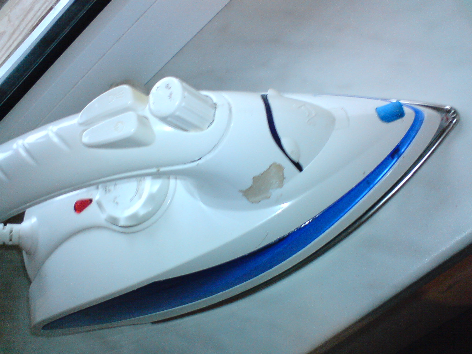
Discharge lamps (for example, neon lamps) are often used as an indicator of switching on. A modern iron works on the same principle, but with some additives. In particular, a thermostat. It is designed for smooth regulation of the voltage supplied to the heating element. By adjusting the tension, we adjust the degree of incandescence of the spiral, and therefore the temperature of the iron. Another addition is a water tank. The cistern is usually built into the body of the iron. The water heats up and turns into steam and at the right moment the steam can be released - this makes the ironing process better. Today, the iron is stuffed with microcontrollers, automatic selection of heating temperature, has a stylish and convenient design, they already have little resemblance to those irons that were created in the distant 17th century. I love puzzles ... especially unexpected ones. Here is such an unexpected puzzle "fell on my head" today. More precisely, it fell not on my head but on my shirt, and did not fall - but fell off. An iron fell apart in my hands, while ironing a shirt…. just like that, the sole took and fell off (it remained hanging on the wires). The case turned out to be one screw that had been unscrewed (the flimsy fastening of the iron soleplate aroused my suspicions from the very beginning), which fastened the sole to the "nose" of the iron. To screw this screw into place, it was necessary to disassemble the entire iron, which was a puzzle. A quick "googling" did not bring a solution and had to "storm" the iron ... So I decided to combine the solution of the puzzle with a photo session. Maybe someone will be useful, although the model of the iron is not known…. but still.. This is how my iron looked at the very beginning, a fallen off potash and an assembled top of the iron:
The heel of the sole is fastened without screws, with some kind of anchor grips)) Ie. the reliability of the design rests on the very screw on the iron spout.
Note that I took the photographs after disassembling the iron ... so there will be a "reconstruction of events" further. So welcome - the iron itself:
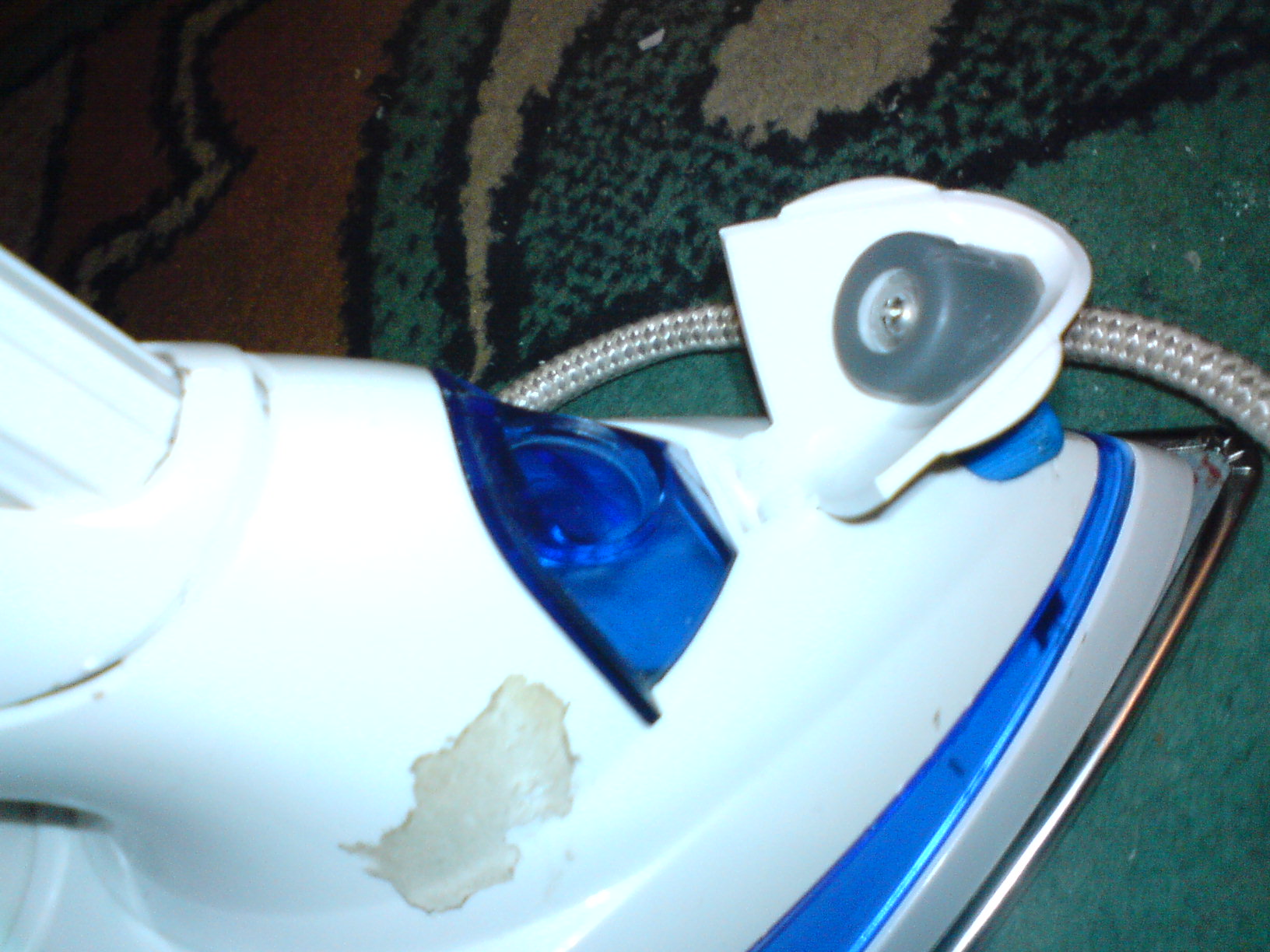
Disassembly should begin with a dastardly hidden screw under the lid of the water tank:
But you need to remove the cover from the closed state, hook it with a screwdriver and lift it up.
Unscrew the first screw:
We take out the "horned bullshit" from the end of the handle and take out the rotary control. To do this, unscrew it counterclockwise until it stops, and then pull it up.
Screw this screw, this is the second hidden screw. I found it only when I was assembling the iron ... I broke it or it was broken before me (the iron is not mine) will remain a mystery !!! In my case, there is an option to buy super-glue or find dichloroethane and glue the plastic:
The next 2 screws are hidden under the cover of the temperature controller. It will have to be brutally ripped out with a screwdriver. (in my case it was easier, I pushed it out from the inside, because the sole had not yet been screwed on)
Unscrew the screws here and near the heel of the sole... There will be 4 more screws: two large and two smaller ...
We remove the part:
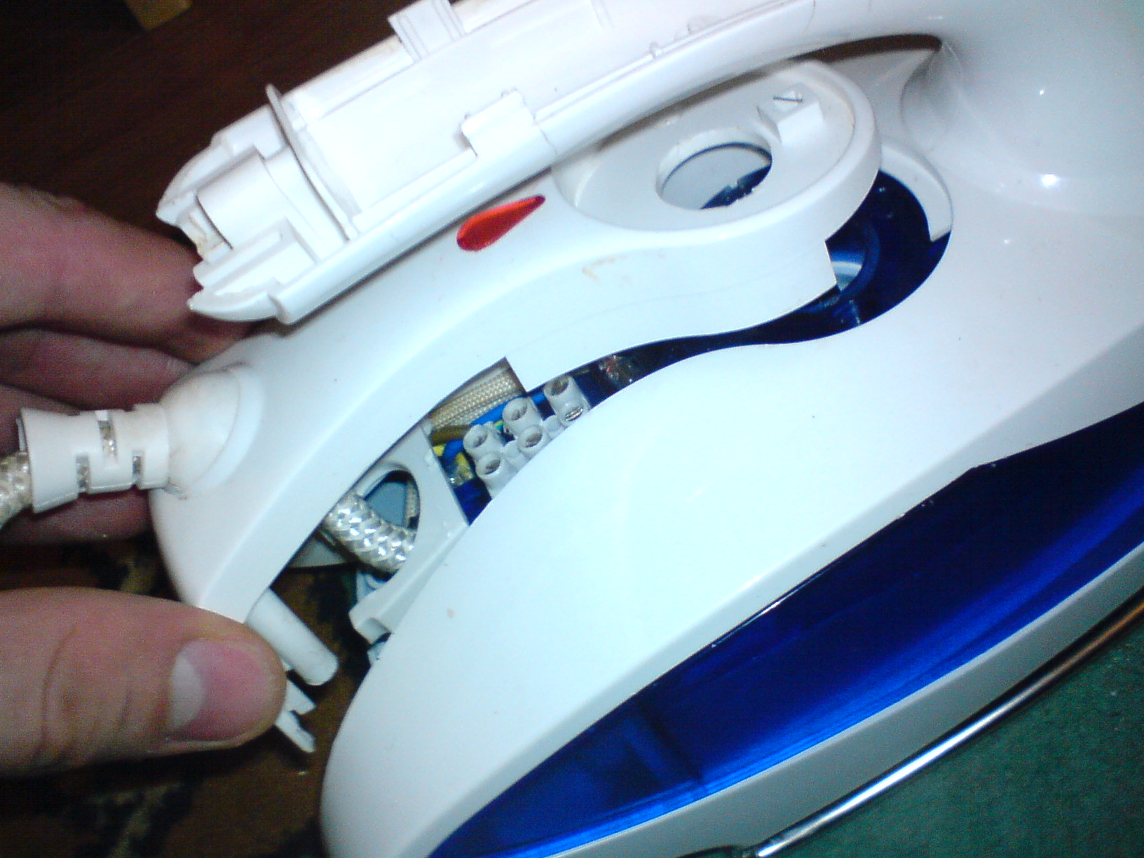
Mesh filters at the bottom of the cylinders ... You also need to watch out and not rip (as I did) the tube leading to the spray on the iron spout:
EVERYTHING, I finally got access to the ill-fated screw on the toe. It can be screwed on and iron assembled. But I recommend checking the integrity and tightness of all contacts. And in general, to carry out maintenance of the iron, the races have already been dismantled…. When assembling, do not forget to put in place various little things so that there are no "extra parts" left after the repair:
two crap I almost forgot to put on. These are some kind of gaskets ... Everything, I tighten the ill-fated screw:
And I start assembling ... in the reverse order to disassembly .... The only thing I will note is that in order to properly assemble the temperature regulator, I unscrewed it all the way clockwise and accordingly knew in which position it was necessary to put on the regulator cover itself ... this was the position of the maximum temperature:
Look like that's it…. do not forget about the screws and do not get nervous during assembly and disassembly)))) This entry was posted on October 5, 2008 at 13:47 and is filed under with tags. You can follow any responses to this entry through the feed. You can, or from your own site. Irons, as household appliances, have appeared for a long time. They were bulky, heavy, and awkward to use. The advantage of these devices was their "indestructibility" due to the simplicity of the design. They became unusable only when hot coal burned through their metal bottom. Today, the iron is a high-tech device, consisting of several units that have precise settings and work well-coordinated. Figure: 1. Repaired iron When all this is violated, the device jumps and eventually fails. This happens for various reasons. Improper operation, dropping the appliance, using chlorinated water for the steam generator and much more. As a result, such a necessary device turns into a useless piece of plastic and metal. What if your favorite device stops heating up? The main thing is not to panic, but to try to return the iron to its working capacity. The cause of the malfunction is often minor and easily remedied. Below, the article will describe how to troubleshoot an electric iron and how to fix it and repair it yourself.
Photo 2 shows a device that does not heat up when it is plugged in and the thermostat wheel rotates.  Figure: 2. We turn the regulator, and the iron does not heat up Figure: 2. We turn the regulator, and the iron does not heat up The mains voltage is present, visually the cord and plug have no visible damage. Judging by the tag (Figure 3), the power of the device is 1000 W. This is not a big indicator, since there are instances of up to 2500 watts. The more watts the iron consumes, the faster it heats up, but more current flows through its circuits and contacts. Therefore, such devices are more likely to be subject to conditions under which they fail.  Figure: 3. Specifications Figure: 3. Specifications As with many irons, you should start by removing the back cover (Figure 4). It is held in place by one screw located exactly in the middle of the cover.  Figure: 4. Remove the back cover Figure: 4. Remove the back cover Use a Phillips screwdriver to unscrew this screw. After the screw is unscrewed, the cover can be freely removed and the incoming electrical circuits of the iron can be seen.  Figure: 5. Electric circuits of the iron Figure: 5. Electric circuits of the iron For ease of installation, there is a terminal block inside (Figure 6), to which the incoming cable comes. On the other side of the terminal block, the wires go deeper into the device. With a high power of the iron in this place, wires may burn out or the terminal block case may melt. The fact is that this method of clamping with screws is not entirely reliable, since over time the connection heats up and the screw looses. In this case, the connection heats up even more and, as a result, the wire burns out. And this place is often a weak link in the electrical circuit of the device.  Figure: 6. Terminal block Figure: 6. Terminal block But everything looks great in the photo. No hints of heating and even less a wire break. This is most likely due to the low power of the heater. But in order to make it convenient to disassemble in the future, it is necessary to remove the cord clamp, which is held by two screws.  Figure: 7.remove the upper part of the iron body Figure: 7.remove the upper part of the iron body Using the same Phillips screwdriver, unscrew one screw and loosen the other. When the cord is free, pull it out and unscrew the case screws.  Figure: 8.Unscrew the screws of the case Figure: 8.Unscrew the screws of the case Now we go to the front. Both screws in this place are under the water container. This is a common spray bottle for irrigating clothes before ironing.  Figure: 9. Press the release button Figure: 9. Press the release button To remove it, press the lock button (Figure 9), and take out the sprayer itself. Next, we take out the container for water.  Figure: 10. We take out the spray Figure: 10. We take out the spray  Figure: 11. Water container Figure: 11. Water container Under it are two screws that fasten the body to the sole of the iron. We unscrew one and then the second screws.  Figure: 12. Unscrew the 2 screws Figure: 12. Unscrew the 2 screws After these manipulations, the top cover can be easily removed.  Figure: 13. Remove the top cover Figure: 13. Remove the top cover All that remains is the sole with the protective casing and electrical circuits.  Figure: 14. Iron sole Figure: 14. Iron sole Photo 15 shows that the indicator lamp is moving away from the terminal block.  Figure: 15. Indicator light Figure: 15. Indicator light It should signal the operation of the iron when the mains voltage is applied directly to the heater. In the center is the thermostat slider (Figure 16) with an oblique guiding cut. This cut is required to dock the regulator wheel on the top cover with the temperature sensor slider.  Figure: 16. Thermostat engine Figure: 16. Thermostat engine We take out the neon lamp from the seat (Figure 17) and unscrew the three screws securing the protective casing of the sole (Figure 18). Next, it is necessary to disconnect the wires going under the casing, otherwise they will interfere. The wires, both incoming and outgoing, have the appropriate color, so there is no need to mark them before disconnecting.  Figure: 17. We take out the light bulb Figure: 17. We take out the light bulb  Figure: 18. Unscrew the 3 fastening screws Figure: 18. Unscrew the 3 fastening screws But before that we check if the problem is in the cord. To do this, we connect the leads of a device capable of testing the circuit with blue and brown wires (Figure 19). These colors correspond to the phase and zero of the 220 V network. We turn the thermostat engine first in one direction and then in the other direction. The device does not show anything, which means that the break is located further under the protective casing.  Figure: 19. Looking for an open circuit Figure: 19. Looking for an open circuit In turn, unscrew all the wire clamps.  Figure: 20. Turn off the rest of the wire clamps Figure: 20. Turn off the rest of the wire clamps Taking out the wires from the clamps, carefully remove the protective cover.  Figure: 21. Remove the protective cover Figure: 21. Remove the protective cover We put it aside and again take the chain pointer. We connect its ends with the terminals of the heater or heating element. The device shows that the heating element is intact, and this is good news, since it is pressed into the sole of the iron.  Figure: 22. Checking the heating element Figure: 22. Checking the heating element Only the temperature regulator remains. A brown wire comes to one of its conclusions, which goes directly from the network. Having connected the device with this output of the temperature sensor (Figure 23), as well as with the white wire that goes to its second contact, we turn the regulator again.  Figure: 23. Checking the thermostat Figure: 23. Checking the thermostat
What can be done in this case? The simplest thing is to replace the regulator. But finding the same one will most likely be problematic, especially a worker. Some people short-circuit the temperature sensor with a piece of wire, thus removing it from the circuit. But this is not an option, since at best, if the iron overheats, the delicate fabric can burn. And at worst, the whole apartment or house, if it is accidentally left plugged in. Therefore, direct connection is not an option. What then can be done? Just readjust the bimetal plate of the thermostat. If you look closely, you will notice that the thermostat contacts are open in any position of the regulator knob. But if you press your finger on the bimetallic plate, the contacts will close at some point. So you need to bend the plate a little and everything should work. We take the "ducklings" and grabbing the bimetal plate with them, slightly rotate it counterclockwise (Figure 24 and 25).  Figure: 24. Rotate the bimetal plate Figure: 24. Rotate the bimetal plate  Figure: 25. Figure: 25. This must be done as carefully as possible and in the middle position of the thermostat engine. At some point, a click will be heard, and the contacts will close. We take measurements after revision (Figure 26). It can be seen that the contact part of the temperature sensor is closed.  Figure: 26. Measurements after revision Figure: 26. Measurements after revision Now we put the wires into the hole in the casing and stretch them with our fingers from the other side. We also lay out the wires carefully. We put on the upper part of the case and tighten the screws that secure it. It is very important that when connecting the body to the sole (Figure 31), the axis of the regulator wheel fits exactly into the cut on the thermostat slider. To check if these two parts are connected correctly, you need to turn the adjuster wheel in different directions. If it is fixed in two directions, then everything is connected correctly and you can continue the assembly.  Figure: 31. We connect the body with the sole Figure: 31. We connect the body with the sole We fix the body with screws and put the container with the spray bottle. Figure: 34. Put back the back cover We turn on the iron and turn the wheel. Photo 35 shows that the iron has turned on and is heating up.  Figure: 35. The iron is running Figure: 35. The iron is running At some point, he turned off himself, having typed the desired temperature. Turn the wheel to maximum, and it turns on again. We can assume that the regulator is working correctly and will not fail at the right moment. At this, the repair can be considered completed. It should be remembered that all work must be done with the device disconnected from the network. |


| Read: |
|---|
Popular:

New
- How to properly have sexual intercourse
- Ovarian aging is not a sentence
- Can i drink alcohol while taking birth control pills?
- What can and should be drunk to get pregnant quickly?
- Frejka pillow sizes by age
- Sports knee brace
- Water programs in X-Fit: training according to the unique SMART SWIM method
- Anti-varicose compression hosiery
- XVIII World Class Games: results
- Oleg Vasiliev: every step in my life is against the movement


